Originally posted by EuphoriX
View Post

-
Re: Broken crybaby 535Q PLEASE HELP!!
Are you sure you changed the dial from the diode position in the pic you posted to the new ohm range towards the left? Just checking. -
Re: Broken crybaby 535Q PLEASE HELP!!
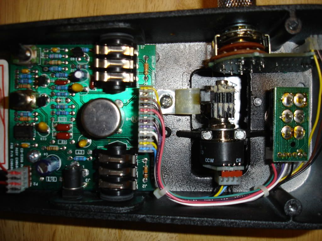
I believe I know how to solder to the 3PDT, but the color codes of the wires on the 535q are unique. I need to know which is which to make the proper connections, and I don't know how to figure that out. I've already tried 2 arrangements of the wires... the first gave a really low, dry output, while the second killed all signal... :/Last edited by EuphoriX; 11-13-2015, 12:06 AM.Leave a comment:
-
Re: Broken crybaby 535Q PLEASE HELP!!
The multimeter setting is not for continuity test. Set the dial to point to hFE mark,when you touch the leads to each other you will get a buzzer sound from the multimeter indicating continuity. Or set it to ohm meter reading, when the leads touch eacxh other the readingwill be shown as zero(or zero error).
Do that & reply back with the results.Leave a comment:
-
Re: Broken crybaby 535Q PLEASE HELP!!
So I found a 3ptd switch from the boost on a pedal I don't use, and am trying to figure out which wires to solder to which pins on the switch... Just like the previous pictures show, there's 6 wires... a red one, green one, dark purple one, light purple one, white one, and a black one, in that order. Anyone know how I would wire these to my 3dpt switch? Also, the swtich is soldered to a small pcb. Do I need to try to desolder it, or if I solder directly to the pins, should I be okay? Thank you for any replies.Leave a comment:
-
Re: Broken crybaby 535Q PLEASE HELP!!
SON OF A B___!!! That first pin is the "effected signal" pin! That's why it works "clean" (off), but not when kicked on... Well, guess it's good I ordered another one from China bout a week ago... Could be herer anytime between now and December 28... -_-Leave a comment:
-
Re: Broken crybaby 535Q PLEASE HELP!!
The first of the 6 pegs on the switch appears to not be continuous.. could this be it? I don't see anything else, but all the other 5 pins on that switch work.Leave a comment:
-
Leave a comment:
-
Re: Broken crybaby 535Q PLEASE HELP!!
Also, your schematic is for the true bypass version. This one's not tb. Old school.Leave a comment:
-
Re: Broken crybaby 535Q PLEASE HELP!!
Did you get it around the right way ?Originally posted by EuphoriX View PostLeave a comment:
-
Re: Broken crybaby 535Q PLEASE HELP!!
I put another tantalum back in. (4.7uF) Everything's continuous, signal passes through when off, goes mute when on... What the Hell...Leave a comment:
-
Re: Broken crybaby 535Q PLEASE HELP!!
Checked it again, and apparently the middle clamp of the input jack is dead... does this make a difference? I mean, signal DOES go through when the pedal is off...Leave a comment:
-
Re: Broken crybaby 535Q PLEASE HELP!!
The uF is all the same, save for the first cap, which is 10 instead of 4.7uF... shouldn't mean it shorts out, just gives the inductor more strength. Voltage is kinda irrelevant... it's all above 18v, so it should be fine.Originally posted by GoldenVulture View PostLeave a comment:
-
Re: Broken crybaby 535Q PLEASE HELP!!
Ended up soldering a wire from the blue lead of the pot directly to the trace that was busted. Full continuity, still no sound.Leave a comment:

Leave a comment: