banner

Announcement

Collapse
No announcement yet.

Ibanez HH 5 Way Switch With Duncans

Collapse
X
 
  • Filter
  • Time
  • Show
Clear All
new posts

  • #16
    Re: Ibanez HH 5 Way Switch With Duncans

    I admire your enthusiasm, the photos turned out great. Nice and large compared to these really static tiny images of a wiring i was looking for a few weeks back where half of it was theory, half was common sense to confirm what I was looking at would work.

    With big puddles of solder on the backs of the pots as long as they aren't a cold solder joint I wouldn't worry about it. If I was to sell a guitar wiring and used parts in previous projects sure I'll clean it off but if it's for myself especially one of my weirder wiring concepts I don't want to mess parts up sure. The work on the switch looks great honestly and how well you soldered in the capacitor and the contacts on the switch and pots you've done a lot better than most people who come in for repairs when I used to do that for extra cash.

    The big tips I tell guys is to continuously poke the iron tip through a brass sponge. I started this habit with my Hakko 888D soldering iron which cost me over 100$ to buy locally but was very worth it. The other is to always apply solder to the end of the wires, a twist and from time to time the tip of the iron. Your technique is good around the contacts of the pots so you're good to go. These are the brass sponges you get on ebay for under 1$ each and I'm still on my original iron tip. I've probably wired up 50-100 projects with this last year.


    Lets get to the wiring
    Your switch looks good with where the wires are going. I even compared it to my actual diagram. At first I was thinking it was a stock ibanez switch they sent you which would be problematic. Just to be sure as Ibanez guitars aren't my specialty so I googled the model number just for 100% reassurance and the 2502N is the 3PS1SC5 so that is correct so we're off to a good start.

    Now the first issue I see. I can see you're going for the 1950s wiring. No doubt about it and I would have done the exact same putting 50s wiring in as I bought a ton of tubular capacitors similar to those. However the way you've got it is technically wrong.

    Also with your guitar is there a string ground of any sort? Traditionally with that type of bridge the wire is fed through the bottom and a big exposed portion of the wire is under the bridge.
    Another case of touching the guitar and hearing buzzing that goes away

    another place you can get string grounding noise which i suspect this is, is if the input jack wires are in reverse

    to do 1950s wiring properly I found this article. Dirk Wacker has tons of great articles on premier guitar about modifying guitars. It's been just under 15 years of tone chasing for me so far and I'm still finding things to try or learning better ways to do stuff. This is the way his article says is the best way to do 1950s style wiring for the tone control.


    this is the fixes I'd do to the wiring. Cool capacitor by the way. My dumb way of remembering the input jack connections is SG like a Gibson. SG...Sleeve ground. Or spot the metal at the base of the input jack. No metal at the base of the contact it's hot lead. No cool catchy thing there.
    Last edited by shadowfire90; 10-19-2019, 11:46 PM.

    Comment


    • #17
      Re: Ibanez HH 5 Way Switch With Duncans

      After cleaning up the volume pot and re-soldering all the ground wires the guitar is now completely silent. My original solder joints were so bad I most likely had several cold joints. Hey, I'm learning, and I'm really enjoying the experience. Now, time to address the tone cap!

      As always, thank you for all the help and insight!

      Comment


      • #18
        Re: Ibanez HH 5 Way Switch With Duncans

        Not a problem I'm enjoying this

        Half the time it's trial and error where the smallest of things can mess with us. The other half the time it's something we'll look back at and laugh at ourselves. I was working on the manager of a branch of Fedex in Canada's guitar and he did a great job soldering but it was a beginner mistake where the volume pot touched the wall of the guitar which had shielding paint. I felt bad so I did a few extra things as he drops the guitar off over night and I had nothing better to do that night. I cleaned it up, polished the frets and all. An old stewmac video I remember someone got a piece of wire about the diameter of human hair and touched a perfectly wired guitar and you watch it go from having signal to nothing.


        The rule of thumb aside from cold solder joints is quite simple
        Make sure no pots contacts touch the wall of the guitar
        It's kind of overkill but i put heat shrink over the exposed bare wires on 4 wire pickups to avoid issues.

        places I'd give the most attention are the left and middle volume contact of the volume. Besides that just check over all the ground wires in the diagram.

        This video I showed someone earlier today and it's extremely helpful if you've got a multimeter. I use mine every day to remove some guess work.
        Last edited by shadowfire90; 10-21-2019, 12:58 AM.

        Comment


        • #19
          Re: Ibanez HH 5 Way Switch With Duncans

          That video was awesome. Thanks for sharing!

          After watching it I busted out my meter and started checking grounds. Everything is perfect except for a few random pole pieces. The screws which should be grounded via the baseplate, however there is zero connection. How do I go about fixing that? All other metal items ground properly, it's just the pole pieces. Should I solder up a ground wire from the screws to the baseplate?

          Comment


          • #20
            Re: Ibanez HH 5 Way Switch With Duncans

            Not a problem, I've learned a few things from him over the years myself. I've never gone as far as testing the pole pieces on pickups. Usually the base plates connection is if I'm switching a 2 wire pickup from 4.

            What type of guitar do you have it may help me figure out a solution.

            With ground it's like a security patrol. Starts at the string ground. Say for example the spring holder on my diagram. Ends at the jack. No over lapping. This is my rules of grounding a guitar. I drew this out 5 years ago.


            and this is how you get some readings on your multimeter for the selections on your pickups. Done right position 2 and 4 will be very low. 2-4k area. This is with a JB/Jazz type setup. 16k and 7.5k roughly.

            The multimeter is a Mastech one that measures a few extra things like capacitors and inductance so for a guitar tech it's a most as this was around 30$, similar to Collin's in the video. The guitar mat you can save some money and get a yoga mat as it'll do the same and cheaper when i was getting into guitar repairs I used t-shirts under the finish. The neck rest is from stewmac and the guitar i wanted to use was my 1980s washburn with 29 frets... BUT.. the active boost in it won't let me read DC resistances as I could on this increasingly rare BC Rich beast.
            Last edited by shadowfire90; 10-23-2019, 06:45 PM.

            Comment


            • #21
              Okay, I just did this I used the 'converted' picture with the SD pickups.
              And I've got problems. Positions 2 and 4 are dead on the switch, no sound, nothing.
              The neck side of the neck pickup is dead. (yes I flipped the magnet, no I haven't cut any wires yet to check the coil).

              Could the problems with positions 2 & 4 be due to a bad coil in the neck? Has anyone had this problem before? And if the coil is bad, will SD replace it? Or am I SOL because I flipped the magnet?

              Thanks.

              Comment


              • #22
                Originally posted by Banner View Post
                Okay, I just did this I used the 'converted' picture with the SD pickups.
                And I've got problems. Positions 2 and 4 are dead on the switch, no sound, nothing.
                The neck side of the neck pickup is dead. (yes I flipped the magnet, no I haven't cut any wires yet to check the coil).

                Could the problems with positions 2 & 4 be due to a bad coil in the neck? Has anyone had this problem before? And if the coil is bad, will SD replace it? Or am I SOL because I flipped the magnet?

                Thanks.
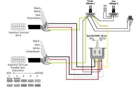
                Okay, I cut the neck pickup loose and checked the wires, both of the coils are showing the resistance, so the neck side of the neck coil isn't bad, it's just not connecting to anything. 2502N is the label on the switch and according to the schematic I've attached, it's correct.
                So, anybody got -any- ideas here? Cause I'm fresh out.Click image for larger version

Name:	5way wDuncans.png
Views:	2755
Size:	165.6 KB
ID:	6015547

                Comment


                • #23
                  Okay, I think I figured this out. First, the neck pickup has to by flipped, as well as the magnet. That wasn't mentioned by anyone (at least not clearly).
                  Next I'm going to check the solder joints on the red / green wires to the neck pickup. Hopefully that'll fix it. I rung out the switch, it's fine. So it the coil.

                  Comment


                  • #24
                    Originally posted by Banner View Post

                    Okay, I cut the neck pickup loose and checked the wires, both of the coils are showing the resistance, so the neck side of the neck coil isn't bad, it's just not connecting to anything. 2502N is the label on the switch and according to the schematic I've attached, it's correct.
                    So, anybody got -any- ideas here? Cause I'm fresh out.Click image for larger version  Name:	5way wDuncans.png Views:	0 Size:	165.6 KB ID:	6015547
                    Glad to hear that the meter readings indicate that your neck pickup is in good order.

                    I'm reviewing the drawing that was converted to SD pup wire color codes, checking that it is error-free. Should be able to get back to you about it later tomorrow.
                    Sanford: "The hardest part about tone chasing is losing the expectations associated with the hardware."

                    Comment


                    • #25
                      These are the kinds of threads I love here. And this is why people keep coming here. Thank you all for sharing your knowledge.
                      Administrator of the SDUGF

                      Comment


                      • #26
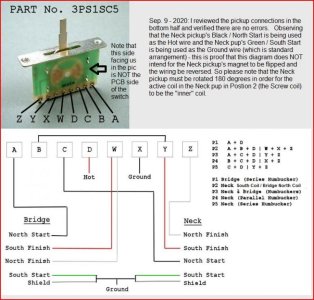
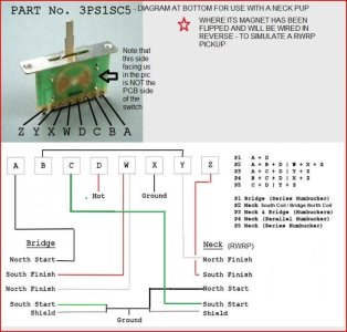
                        Alright, so that diagram above that was updated to use SD wiring color codes has a few errors. It was easier for me to start with a fresh drawing. But I will mention quickly that the "converted" drawing's errors above include the Hot connection from the switch going to ground, and the ground connection from the switch going to Hot. Also, that diagram is not designed to accomodate a Neck pickup whose magnet has been flipped, like is the case for your Neck pickup.

                        I used as my basis, the diagram available on the internet that is a schematic for how the 3PS1SC5 switch works - and it has at the bottom of it a diagram for how to wire to pickups using Seymour Duncan wiring color coses. I added some further explanatory notes into that diagram. That's the first diagram below HOWEVER - you can't use that one because you already flipped the magnet in your Neck pickup, and the original diagram is designed for a Neck pickup where the magnet has not been flipped.

                        So, you will use the 2nd diagram below, which is a version I created based on the 1st one but properly accomodates a Neck pickup whose magnet has been flipped.

                        Please review the two diagrams and the notes made in each and let me know if this all makes sense now. And again. you will want to use the 2nd diagram, not the 1st, because the magnet has been flipped in your neck pickup.

                        Sanford: "The hardest part about tone chasing is losing the expectations associated with the hardware."

                        Comment


                        • #27
                          Originally posted by shadowfire90 View Post
                          Re: Ibanez HH 5 Way Switch With Duncans

                          This will work. No need to physically flip the magnet or anything. The reason they tell us to is that in position 2 with this particular Ibanez wiring is that it would not be hum cancelling if you chose not to flip the color code on a pickup in position 2. I've seen it first in the fender showmaster so I call it the showmaster wiring. It has a nice ring doesn't it. Or at least more memorable than a TV remote like model.

                          This is what you'd do. Without that Cortek switch I wish someone told me that it's an impossible wiring 2-3 years ago. I made the mistake of trying this with a basic 5 way import switch with no name import 4 wire pickups assuming I didn't know the color code properly. Then I found the youtube video that is probably print screened from where the man described the pin layout of that switch. I learned a lot about pickups and wiring from that endeavor but regardless this is what you'll want to do.
                          [ATTACH=CONFIG]101499[/ATTACH]
                          I have been down this path 3 times Installing DImarzio's into Ibanez Guitars using that same schematic if memory serves. You should not need to flip a magnet to get anything hum cancelling if you are using the Ibanez switch. Its not the same as switch commonly found in import guitars. Its modified to do the 2 Hum / 5 position options they offer. I bought them through Reverb:

                          Ibanez 3PS1SC5 - 5 Way Lever Switch (HH Configuration) Split 5

                          Comment


                          • #28
                            Originally posted by Banner View Post
                            Okay, I think I figured this out. First, the neck pickup has to by flipped, as well as the magnet. That wasn't mentioned by anyone (at least not clearly).
                            Next I'm going to check the solder joints on the red / green wires to the neck pickup. Hopefully that'll fix it. I rung out the switch, it's fine. So it the coil.
                            If your using the ibanez switch, that should not be necessary

                            Comment


                            • #29
                              So I just recently rewired my old Jackson using the Ibanez 2502N 5-way switch and the diagram posted. All switch positions work fine and no grounding issues. I am however losing volume on positions 2 and 4. Is this to be expected?


                              Sent from my iPhone using Tapatalk

                              Comment


                              • #30
                                The pickups might be out of phase. Grab an ohmmeter and find out what are the 4 wires - North start, North finish, South start, South finish. See this page for colour codes used by the most common pickup makers:
                                Anderson, Bare Knuckle, Bartolini, Benedetto, Bill Lawrence, Caparison, Carvin, DiMarzio, Dunca Designed, EMG-HZ, Fender, Fralin, GFS, Gibson, Golden Age, Gotoh, Ibanez, Iron Gear, Joe Barden, Jackson, Kent Armstrong, Lace, Lollar, Lundgren, Nordstrand, Paul Reed Smith, Peavey, Railhammer, Rio Grande, Rockfield, Seymour Duncan, Shadow, Sheptone, Suhr, Swineshead, TDM, Tone Rider, TV-Jones WCR and more.

                                Or, just flip the magnet in one of them.

                                Comment

                                Working...
                                X