

 Tweet
Tweet
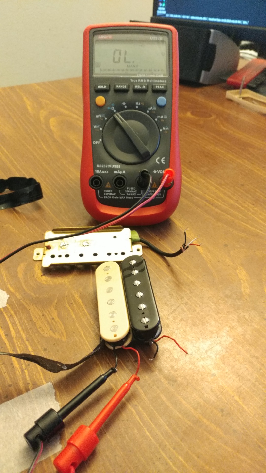
Re: Multimeter shows pots resistance instead of pickup resistance when connected to j
Cool Thank you so much. I have made that change. Please check if my drawing is not faulty. Few questions though that puzzle me.
1. The bridge tone CAP is going to 1st switch position BUT Neck tone CAP is NOT going to 1st switch position on Neck POT but is being grounded to the POT? Isn't that suppose to be same/universal setup for both tone POTS?
2. BOTH tone POT left lugs (marked with black dot on them) are NOT suppose to be ground to the back of the pot. Just left the way they are?
3. Is that black jumper cable is grounding POTS then?
4. I would also ADD ground cable in C letter shape to ALL POTS, which then would run to bridge post cable ground? OR
5. Are all pots grounded now due to black jumper wires?

Thank you kindly again.
Cool Thank you so much. I have made that change. Please check if my drawing is not faulty. Few questions though that puzzle me.
1. The bridge tone CAP is going to 1st switch position BUT Neck tone CAP is NOT going to 1st switch position on Neck POT but is being grounded to the POT? Isn't that suppose to be same/universal setup for both tone POTS?
2. BOTH tone POT left lugs (marked with black dot on them) are NOT suppose to be ground to the back of the pot. Just left the way they are?
3. Is that black jumper cable is grounding POTS then?
4. I would also ADD ground cable in C letter shape to ALL POTS, which then would run to bridge post cable ground? OR
5. Are all pots grounded now due to black jumper wires?
Thank you kindly again.


Comment