
 Tweet
Tweet
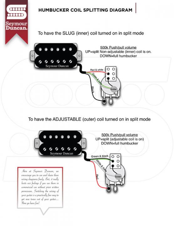
In the lower part of this diagram (the one that splits the humbucker to the adjustable/outer coil), would it make any difference if the Red and Green wires were swapped with each other? I am thinking "no" (?)

-
Sanford: "The hardest part about tone chasing is losing the expectations associated with the hardware." -
Re: Another "why is this wiring diagram done like this?" question
The two coils would then be out of phase with each other, right? -
Re: Another "why is this wiring diagram done like this?" question
In a one pickup guitar, no. With two pickups swapping the red and green wires on one pickup will put it electronically out of phase with the other pickup.Originally posted by kingswebe View Post
Edit: When I wire a pickup to split to the screw coil, I use the typical red and white pair with the green grounded and black connected to the pot input lug. I then connect a jumper between the pot input and the closest switch lug. With the pot down, you get your usual series wiring. With the pot pulled, the red gets connected to the pot input and the slug coil is shorted start to finish.Last edited by dystrust; 06-18-2019, 09:25 PM.Originally posted by crusty philtrumComment
-
Re: Another "why is this wiring diagram done like this?" question
Yes.Originally posted by PFDarkside View Post
No, no, no. You missed what he asked. On the bottom diagram, if you reverse red & green, that pup will be out-of-phase, (reverse polarity), with itself, in the normal series mode. It will be thin and lifeless when used by itself. When split, it will be ok by itself, but again, thin and weak when used with the other pup.Originally posted by dystrust View Post
Which begs the question . . . why does the OP want to deviate from the original, (working), configuration?Comment
-
Re: Another "why is this wiring diagram done like this?" question
I am having trouble picturing the jumper setup you described.Originally posted by dystrust View Post
"I use the typical red and white pair with the green grounded and black connected to the pot input lug." This sounds like what is depicted in the top half of the pic i posted (?) Also, which lug on the push-pull are you referring to as "the closest one"?Sanford: "The hardest part about tone chasing is losing the expectations associated with the hardware."Comment
-
Re: Another "why is this wiring diagram done like this?" question
Good catch. I was thinking of what would happen with the green to hot, black to ground, and red/white together.Originally posted by ArtieToo View PostOriginally posted by crusty philtrumComment
-
Re: Another "why is this wiring diagram done like this?" question
This is a Jimmy Page diagram, but the neck pickup is wired like I described:Originally posted by kingswebe View Post
 Originally posted by crusty philtrum
Comment
-
Re: Another "why is this wiring diagram done like this?" question
Artie, thanks but no, i do not want to deviate. I just did not understand why red wire was being used as a hot lead instead of green..... and i can't say i actually understand yet why reversing red and green would make the humbucking mode out of phase other than you said it would... but i will ponder it furtherOriginally posted by ArtieToo View PostSanford: "The hardest part about tone chasing is losing the expectations associated with the hardware."Comment
-
Re: Another "why is this wiring diagram done like this?" question
SD's standard color codes are:Originally posted by kingswebe View Post
GREEN = start of adjustable/south coil
RED = finish of adjustable/south coil
BLACK = start of stud/north coil
WHITE = finish of stud/north coil
In their standard series humbucker wiring, they connect the to finish wires together, with one of the start wires(black) as output and the other(green) as ground. The diagram uses red as output because it's pairing the green and black together instead of the typical red and white pair.Originally posted by crusty philtrumComment
-
Re: Another "why is this wiring diagram done like this?" question
Agreed, but i was wondering why the diagram was pairing black and green together in the first place, vs red and black. And Artie is saying the reason why, is in order to avoid phase issues. Which i am sure Artie is correct , i just need fo study it further in order to "see it".Originally posted by dystrust View PostSanford: "The hardest part about tone chasing is losing the expectations associated with the hardware."Comment
-
Re: Another "why is this wiring diagram done like this?" question
So, i looked at it further, and i don't get it. If in the first diagram where the pickup splits to inner coil -that one does not have phase issues if the North *start* wire is the one that is used as a Hot Lead, why is it a phase issue in the other diagram to use the other "start" wire (green) as the Hot lead?.. just trying to gain an understanding...Originally posted by ArtieToo View PostSanford: "The hardest part about tone chasing is losing the expectations associated with the hardware."Comment
-
Re: Another "why is this wiring diagram done like this?" question
If you only flip the wires of one coil (red and green), but not the other (black and white) you will put one coil out of phase with the other coil.Originally posted by kingswebe View Post
Comment
-
Re: Another "why is this wiring diagram done like this?" question
Yes, everyone has been saying that, but not *why* that is the case.Originally posted by beaubrummels View Post
This article at 1728.com helped me understand why. Particularly, that the windings on each coil are NOT actually wound reverse to each other as i thought. Instead, it is how the current is directed through each coil via the wiring connection choices that determines whether the two coils are electrically reverse from each other or not. Note that the diagrams in this article use Dimarzio's wire coloring codes, not Seymour Duncan's
So in the part of the diagram i posted originally that i was asking about, if Green wire were made to be the hot lead, this would have the current travel clockwise through the South coil to reach the Red wire. The way current flows after that through the North coil because Red would be connected to Black would result in the North coil also having a clockwise direction of current travel. That would result in an out of phase result, because the direction of current travel through the two coils needs to be opposite /"reverse" of each other.Sanford: "The hardest part about tone chasing is losing the expectations associated with the hardware."Comment
-
Re: Another "why is this wiring diagram done like this?" question
The only reason for the seemingly "reverse" wiring is to make it a teeny bit easier to wire the split switch. Doing it this way allows both pickups to be split by shorting the series link to ground, in order to split to the two different coils. The same thing could also have been accomplished by using the normal wiring, and shorting the red/white pair to "hot", or black.Originally posted by kingswebe View Post
Think of it like this. Fig 1 shows normal humbucker wiring. I can rotate the bottom coil around, (for illustration purposes), so that both coils are in a straight line. (Fig 2) I haven't changed anything electrically. Now I can change the physical position of the two coils as in fig 3. As long as both black and red point toward positive, and green and white point toward ground, I haven't changed anything electrically, or polarity. But now you can see that grounding the red/white of fig 2 shorts out the screw coil, and grounding the green/black of fig 3 shorts out the stud coil.
Does that make sense, or did I confuse you more?
Comment
-
Re: Another "why is this wiring diagram done like this?" question
Artie, thanks, but honestly the transition from Figure 2 to Figure 3 in your example would not have made sense to me if i had not already read the 1728.com article that covers direction of current flow and how that impacts the "wind" result for each coil.Originally posted by ArtieToo View PostLast edited by Jack_TriPpEr; 06-19-2019, 08:28 AM.Sanford: "The hardest part about tone chasing is losing the expectations associated with the hardware."Comment
Comment