4-Way Tele V/V/T Schematic Help

idsnowdog

Imperator of Indignation
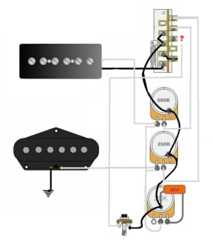
I drew up this schematic with two volumes and one tone. Terminals 2 and 3 on the right are tied together on the original and go to the volume. The pickups go to the volumes first and then from the switch to the output in mine. Are 2 and 3 still tied together?
 

Attachments

  • modified.png
    modified.png
    109.6 KB · Views: 0
  • original.png
    original.png
    112.3 KB · Views: 0
Are we sure the original diagram worked? To my eye, it looks like position 2 and 3 are just the neck and 4 does nothing. Someone else can check me on that.
 
Looks like 1 and 4 never connect to hot and wouldn't make sound.

(Can't edit). What is each position supposed to do, exactly?
 
Are we sure the original diagram worked? To my eye, it looks like position 2 and 3 are just the neck and 4 does nothing. Someone else can check me on that.
The original is the same as SD's 4-way schematic. Both could be wrong, but I doubt that.
 

Attachments

  • Untitled.png
    Untitled.png
    146.9 KB · Views: 0
The 1st diagram is horrible. The bridge is always on, and the neck "hot" is always connected to the output. It's turned "off" by lifting it's ground. So, in the bridge-only position, you'd have the possible noise of the single bridge + the constant noise-hum-buzz-radio stations of the neck. You'll get more noise than Tele.

I need to study the other one to see what's going on, but like beau asked . . . what's the desired configuration.

Edit: You posted when I did. Let us study that some more.
 
Back
Top