Jack_TriPpEr
Well-known member
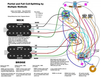
I recently completed a wiring scheme that allows one to demo different methods of coilsplitting - both partially and fully splitting the humbuckers, and wanted to share it for anyone potentially interested. I have vetted this scheme by wiring up one of my two humbucker guitars wuth it and checking that all the options shown do work without issue.
The intent of this scheme is to allow you to A-B compare different methods for how two humbuckers can have one of their coils partially or fully cut/split, and which coils you prefer to cut and which you prefer to leave active, both individually, and as pairs of coils to be combined together, i.e. Both Inners, Both Outers, etc.
** Please note that this scheme is meant to be used for TEMPORARY demo purposes only, so one can figure out which FEW of the multiple configurations present that you actually like, and then rewire your guitar after that with just those few options that you liked. Versus keeping it wired this way which doesn't "leave room" to have other common options you may want, like an Out Of Phase switch, or Master Series/Parallel switch, etc.
With this scheme, you get Spin-A-Split capabilities for two humbuckers plus:
1) can switch each pickup so its coils are wired In Parallel and apply a full or partial coilsplit.
2) choose which coil of each pickup you want to partially or fully cut
3) when the Pickups are in Parallel mode, turn on or off whether the signal of the cut coil is run through a Resistor & Capacitor before being sent to Ground (for EQ shaping purposes).
The diagram has numerous notes that detail what happens when each switch is in the up or down position, the value of the pots to be used (especially pertinent for the Spin-a-Split pots), the value of the caps, etc.
**EDIT: the dual-gang pot used for the Spin-A-Split for both humbuckers needs to be a No Load type. You can buy one designed like that or DIY it yourself. Here is a link to one video on YouTube that shows how to DIY A No Load:
https://youtu.be/dN3SlH-cEAg
The idea of coil-splitting a humbucker wired In Parallel came to me after musing about the possibilities of a scheme forum member Gstring posted last September where he used a fixed resistor and cap in series on the ground side of one coil in a humbucker wired in parallel. You can find more details about that scheme and Gstring's thoughts on what the resulting tone was like from doing that, in the thread at this link:
https://forum.seymourduncan.com/foru...ut-appreciated
(^ fixed the broken link above)
FYI: in Parallel mode, the coil is being cut by disconnecting its *Cold wire* from ground. FYI: This also means that when the coil is fully cut in this manner, there is the potential for added RF noise/interference (assuming the volume pot for that humbucker is not turned down to 0), because the Hot wire is still connected and getting signal from the jack, i.e. it's a dangling live antennae.
It's already late in the evening as I am writing this, so I may be forgetting to mention some things and I apologize for that. but I will revisit it tomorrow and add whatever important notes/descriptions I may have missed.
** There is no pickup selector switch in this version of the scheme because my guitar didn't have enough pot holes for it and the other switches and pots required by this scheme - but an alternate version cpuld be created to replace the two individual volume pots with a 3 way toggle and master volume w S1 - as long as you have an additional ole in the control cavity dor the 2nd 4PDT switch currently shown on the 2nd individual volume pot. The posted diagram uses Independent wiring of the Neck and Bridge volume controls to compensate for lack of a pickup selector switch.
For those whose browsers display the details of the attached diagram as fuzzy when they zoom in, following is the link to this diagram loaded to my Imgur account:
https://imgur.com/gallery/TMo4Dmv
Attachments
Last edited: