Does this master series-parallel wiring diagram seem valid?

Jack_TriPpEr

New member
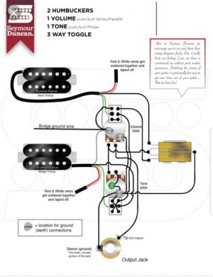
I want to wire up a master series-parallel option for 2 humbuckers using a push-pull switch, and the wiring scheme depicted in the wiring diagrams that are available here on the SD site don't make sense to me (being someone who doesn't fully understand electrical theory).

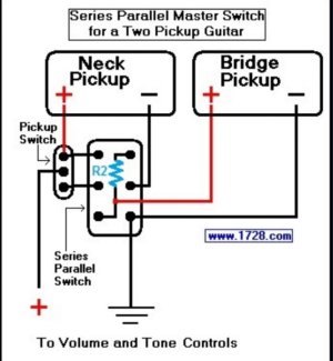
So i looked on the net and found this alternate wiring scheme that does make sense to me.

Before i take the time to wire this up, is there anyone here who can validate that this wiring scheme will actually work as advertised?

Thanks!

1544152731507.jpg
 
Re: Does this master series-parallel wiring diagram seem valid?

If the two red arrows are joined together, then it does what it says!
Otherwise if you connect the two red arrows to different points on the selector switch, you are going to have a non-functional input position when you select series mode.

By "non-functional input position", do you mean no signal output i.e. silence?
 
Re: Does this master series-parallel wiring diagram seem valid?

By "non-functional input position", do you mean no signal output i.e. silence?

Yes, there would be silence in one position as the connection from the DPDT switch will not pass any signal when you select series mode.

I'm not totally clear on how many humbuckers you will install and what the pickup selector will be. Anyway I suggest to draw out the overall wiring diagram before you finalise the choices.
 
Re: Does this master series-parallel wiring diagram seem valid?

Each pickup has to go to its own volume pot or its own lug on the selector switch, otherwise you’ll have two pickups on all the time. But the diagram looks right.
 
Re: Does this master series-parallel wiring diagram seem valid?

Each pickup has to go to its own volume pot or its own lug on the selector switch, otherwise you’ll have two pickups on all the time. But the diagram looks right.

Thank you Beaubrummels. I had interpretted the diagram in the same way, and that would be fine with me.

But Teleplayer seems to say above each pickup output needs to go to the SAME lug on the pickup selector , or else i'll get no signal output. Any comment on that? Based on two other wiring diagrams that show the pickup outputs going to different pickup selector lugs, i tend to think that the outputs should not go to the same lug on the pickup selector.
 

Attachments

  • 20181129_101032.jpg
    20181129_101032.jpg
    48.5 KB · Views: 0
  • 20181207_075119.jpg
    20181207_075119.jpg
    47.1 KB · Views: 0
Last edited:
Re: Does this master series-parallel wiring diagram seem valid?

But Teleplayer seems to say above each pickup output needs to go to the SAME lug on the pickup selector , or else i'll get no signal output. Any comment on that? Based on two other wiring diagrams that show the pickup outputs
going to different pickup selector lugs, i tend to think that the outputs should not go to the same lug on the pickup selector.

I wrote that there will be a non-functional input position. The Seymour Duncan wiring diagram in the post above has this issue, since it uses effectively the same wiring for the DPDT that's in your first post. When you put switch in "Series mode" you will need to put the pickup selector in either Neck or Middle position. In "Series mode" with the pickup selector on Bridge position you will only get silence.

The "1728.com" wiring diagram avoids this issue as you will get series mode no matter where the pickup selector is positioned. I'm not sure what the "R2" resistor is for, but it would be ok to replace it with a link.
 
Last edited:
Re: Does this master series-parallel wiring diagram seem valid?

I wrote that there will be a non-functional input position. The Seymour Duncan wiring diagram in the post above has this issue, since it uses effectively the same wiring for the DPDT that's in your first post. When you put switch in "Series mode" you will need to put the pickup selector in either Neck or Middle position. In "Series mode" with the pickup selector on Bridge position you will only get silence.

The "1728.com" wiring diagram avoids this issue as you will get series mode no matter where the pickup selector is positioned. I'm not sure what the "R2" resistor is for, but it would be ok to replace it with a link.

Teleplayer, sorry about that, i did not understand fully until your last reply. For some reason i wasn't mentally connecting that "one non-functioning input position" meant specifically one of the 3 pickup selector positions. Ok, so the Rothstein and Seymour Duncan diagrams require the player to set the pickup selector to anything but middle position when in series mode or else there will be no signal output. Thanks much for also pointing out that the 1728.com wiring scheme does not have this "extra action requirement"- i am going to use the 1728.com diagram because of that.
Thank you!
 
Last edited:
Re: Does this master series-parallel wiring diagram seem valid?

If you think about it, it doesn’t make sense to throw the series switch unless you had both pickups on. I’ve seen diagrams where the series switch overrode the selector, but I can’t remember the trick. The ‘dead’ position Teleplayer referees to is a known issue with Jimmy Page wiring.
 
Re: Does this master series-parallel wiring diagram seem valid?

If you think about it, it doesn’t make sense to throw the series switch unless you had both pickups on. ..

Disagree. Here's one scenario i plan to use that feature frequently.

1) non-series mode. pickup selector in bridge only mode. Using amp high gain channel for crushing high gain passages in a song.
2) punch amp channel selector to switch from high gain channel to clean channel. Hit series/parallel switch to series - to combo bridge bucker with neck single coil for much better clean tones than just the too-hot and grainy bridge bucker by itself.
3) clean passage of song is over. Punch amp channel selector to change channel back tobhigh gain, then set series/parallel switch back to non-series mode. Back to crushing high gain tones, without having to take a 3rd action of also messing with the pickup selector switch, which has been set to bridge only the whole time.

The series/parallel mode when wired like that. Is like a 4th position on a 3 way toggle switch, that you dont have to switch thru each intermediate pickup selection choice. E.g. Go from 4th to 1st directly back and forth , or 4th to 2nd directly back and forth directly, etc. Its great.
 
Last edited:
Re: Does this master series-parallel wiring diagram seem valid?

I wrote that there will be a non-functional input position. The Seymour Duncan wiring diagram in the post above has this issue, since it uses effectively the same wiring for the DPDT that's in your first post. When you put switch in "Series mode" you will need to put the pickup selector in either Neck or Middle position. In "Series mode" with the pickup selector on Bridge position you will only get silence.

The "1728.com" wiring diagram avoids this issue as you will get series mode no matter where the pickup selector is positioned. I'm not sure what the "R2" resistor is for, but it would be ok to replace it with a link.

Just wanted to report in that i got the master series-pull functionality wired up earlier today using the 1728.com diagram, and it works like a champ. And i am loving how i the pickup selector is non-functional when the switch is in series... that is letting me go from a nice in series sound directly back to bridge only in parellel mode, very handy.

Thanks again Teleplayer!
 
Re: Does this master series-parallel wiring diagram seem valid?

Sorry to resurrect an old thread, but I think I'm in Jack's position and want to properly understand the info here. Jack, would I be right in saying that when you used the 1728.com diagram, flipping the switch gives you both pickups in series, no matter what position the selector switch is in?
I plan on implementing the mod on a 335 with '50s wiring. Originally I assumed that most series/parallel diagrams would only effect the middle position, like you switch to the mid pos with the push/pull up and the pups are in series, or down and they're in parallel, but I see the appeal of a push/pull that bypasses the selector: say you're using the neck pup and you want to switch to the middle position in parallel, you use the selector switch like normal, but say you're using the neck pup and wanted to use both pups in series, you pull the push/pull. Either of the desired results only require one action.

DenDenDen,

Yes, you are interpretting it correctly.

I did not re-read all the prior replies in this thread, so I apologize if I am repeating something that is already mentioned above, but be aware that some diagrams that feature a master series-parallel switch can be wired differently where the pickup selector switch is not completely overriden - and in those cases, some of the positions of the pickup selector switch could either duplicate another position and or have a killswitch type result.
 
Re: Does this master series-parallel wiring diagram seem valid?

Yes, you are interpretting it correctly.

Thank you for clarifying! Can I ask what your results were, and what kind of guitar wiring you implemented the switch into?
Like I said I plan on doing this in a 335 with the tone controls wired to '50s spec. Because it's a guitar with four pots, the pickups are wired to the pots and not the selector switch (like they would be in a guitar with only a master Vol+tone) so I've had to draw out a diagram that uses the 1728.com switch, but the top left and middle left lugs go to each volume pot instead of the selector shown in the diagram.

Hope that all makes sense, thanks for getting back to my last post.
 
Re: Does this master series-parallel wiring diagram seem valid?

Thank you for clarifying! Can I ask what your results were, and what kind of guitar wiring you implemented the switch into?
Like I said I plan on doing this in a 335 with the tone controls wired to '50s spec. Because it's a guitar with four pots, the pickups are wired to the pots and not the selector switch (like they would be in a guitar with only a master Vol+tone) so I've had to draw out a diagram that uses the 1728.com switch, but the top left and middle left lugs go to each volume pot instead of the selector shown in the diagram.

Hope that all makes sense, thanks for getting back to my last post.

I installed this on a guitar that had a Master Volume and Master Tone control. But the fact that your guitar has the 2 individual pots per pickup should not cause a problem.

However, you do want to have each pickup continue to *first* route through each of those two controls before routing to this control and the pickup selector switch. I may have misunderstood what you mean in your last reply about the top left and middle lugs, but it seems you are planning to route to the volume and tone controls in oppostite order of what I just described.
 
Re: Does this master series-parallel wiring diagram seem valid?

you do want to have each pickup continue to *first* route through each of those two controls before routing to this control and the pickup selector switch.

Oh man, I did not know this. I think you've understood me correctly. I have a complete diagram, but I drew this so that it's easier to see what I'm planning to do with the switch. The yellow highlighter just differentiates hot from ground. This drawing just substitutes the selector switch for volume pots in the original diagram. So I need to take the pickups' hot wires to the volume and tone pots, and then the DPDT to the selector switch. I guess the pickups' grounds just go straight to the DPDT?
Thank you for setting me straight with this, I'd really like to be able to implement this mod if I can.

KlF8Oci.jpg
 
Last edited:
Re: Does this master series-parallel wiring diagram seem valid?

Thank you for clarifying! Can I ask what your results were, and what kind of guitar wiring you implemented the switch into?
Like I said I plan on doing this in a 335 with the tone controls wired to '50s spec. Because it's a guitar with four pots, the pickups are wired to the pots and not the selector switch (like they would be in a guitar with only a master Vol+tone) so I've had to draw out a diagram that uses the 1728.com switch, but the top left and middle left lugs go to each volume pot instead of the selector shown in the diagram.

Hope that all makes sense, thanks for getting back to my last post.

Can you post a diagram of your proposed revision? I want to be sure I'm understanding your proposal correctly. If your proposal is to place the volume pots between the 3-way and the push/pull, it's not going to work. I'd prefer to see a diagram to be sure I'm understanding what you're saying.

Series modes in 2V guitars is tricky. When both volume pots are in the series, they both function as master volume controls, yet they have different tapers and roll off high frequencies differently. That's why my preference is to lift a pickup from its volume control in series mode, but the 1728.com diagram doesn't have enough poles for that.

Edit: I should have refreshed before posting... you did post a diagram, but a partial one. Can you post the entire thing?
 
Last edited:
Re: Does this master series-parallel wiring diagram seem valid?

Can you post the entire thing?

I'll post the entire thing but it might be a little confusing because I only drew it as a reference for myself, not to be interpreted by anyone else haha.
I'll explain it so it's easier to understand. It's made a little more confusing by the fact that I'm using Bare Knuckle P90s with "2 conductor, plus screen" wiring to allow me to do this mod. So each pup has three leads, though in the diagram the bridge pickup's screen and ground are twisted together. A "+" next to a lug or wire means it's the pup's hot, a "-" is the cold, and an E (for Earth) is the screen. The highlighter just differentiates the neck pickup wiring from the bridge's.

I just quickly added in the wiring to tone pots and switch, as that wasn't on there yet as I wouldn't have really needed a diagram to do that part when I came to wiring it up. Does this still qualify as '50s wiring?
Thanks for your help!

mOdt6pg.jpg
 

Attachments

  • FF0gOtv.jpg
    FF0gOtv.jpg
    30.2 KB · Views: 0
Re: Does this master series-parallel wiring diagram seem valid?

I could try redrawing the diagram with some colour coding to make it clearer, like I said this diagram wasn't meant for anyones eyes other than my own haha
 
Re: Does this master series-parallel wiring diagram seem valid?

I'll post the entire thing but it might be a little confusing because I only drew it as a reference for myself, not to be interpreted by anyone else haha.
I'll explain it so it's easier to understand. It's made a little more confusing by the fact that I'm using Bare Knuckle P90s with "2 conductor, plus screen" wiring to allow me to do this mod. So each pup has three leads, though in the diagram the bridge pickup's screen and ground are twisted together. A "+" next to a lug or wire means it's the pup's hot, a "-" is the cold, and an E (for Earth) is the screen. The highlighter just differentiates the neck pickup wiring from the bridge's.

I just quickly added in the wiring to tone pots and switch, as that wasn't on there yet as I wouldn't have really needed a diagram to do that part when I came to wiring it up. Does this still qualify as '50s wiring?
Thanks for your help!

View attachment 105407

So one thing minimally you will want to change, is to separate the shield/screen from the "cold/-" of the pickup. The shield/screen will still get grounded, but just separate from the pickup's "cold/-". This is done to prevent the EMI/RFI noise present in the signal of the "shield/ground" from getting fed into the output signal when that pickup's "cold/-" is daisy chained In Series with the other pickup. That would add unnecessary noise to your output signal.

I am interested in seeing what additional changes Mike S ends up suggesting as well.
 
Last edited:
Back
Top