Help understanding 5-way super switch wiring diagram

gesp

New member
Hey everyone,

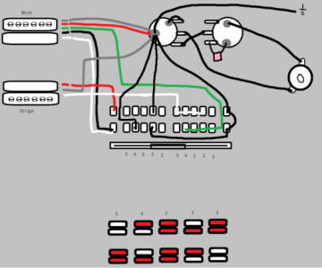
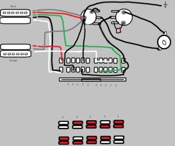
I've recently bought a 5-way super switch and rewired my guitar in the following manner:


You'll also find the switch position result above. I've wired two pickups: Dimarzio Air Norton (Neck) and Ibanez Quantum (Bridge).

I actually got the result I wanted from the pickup positions, but my question is that I'm not sure what I'm doing in positions 2 and 4. Is this a coil-split of both neck and bridge pickups (outside and inside) or is this coil-tapping ir something else? If so, why is it that way?

Ant suggestions on how to make this wiring better?

Thanks!
 

Attachments

  • photo108887.png
    photo108887.png
    98.5 KB · Views: 0
  • sketch1677568359404~2.png
    sketch1677568359404~2.png
    96.9 KB · Views: 0
  • photo108889.png
    photo108889.png
    96.9 KB · Views: 0
Last edited:
For a start, that diagram doesn't do anything but ground out all the pickups in all combinations. Nothing ever goes from the switch to the hot input of the volume pot.

From the coil color diagram, it appears you are trying to get inside and outside coils in 2 and 4. But you would need opposite coils to keep it hum-cancelling, e.g. mate a screw coil with a slug coil (but you've got two different brands of pickups, so I don't know if the coil wind direction and magnet polarity are the same or not.)

You're right! Just noticed I had it wrong. I updated the diagram. Can you please check now?
 
Last edited:
When I did this with SD pickups, I had to flip a magnet in one humbucker to make it all hum-cancelling. No idea if you need to do that or not.
 
I think it's getting closer, but I'm not seeing where the bridge gets split differently between 2 and 4. I see a bridge split on 2 but nothing on 4. But maybe I'm reading it wrong. Someone else may need to check me.
 
I think it's getting closer, but I'm not seeing where the bridge gets split differently between 2 and 4. I see a bridge split on 2 but nothing on 4. But maybe I'm reading it wrong. Someone else may need to check me.

I've looked back at the wiring and confirmed that what I have on the wiring diagram is giving me the result below. But I'm not really sure what I did, to be honest, so I wanted to understand how I made the pickup split and what kind of split it is.
 
If you tap on the poles of the coils with something metal (like a screwdriver or allan wrench) in each switch position, are you saying the exact coils colored in red are active, correctly in each position? (That's not what I might expect based on the diagram.). But that is the best way to check, at this point.
 
If you tap on the poles of the coils with something metal (like a screwdriver or allan wrench) in each switch position, are you saying the exact coils colored in red are active, correctly in each position? (That's not what I might expect based on the diagram.). But that is the best way to check, at this point.

Yeah, touched each position and verified. Why wouldn't you expect this to happen? How would you improve the wiring and get the same result?
 
Back
Top