Help with schematic.

ekalks

New member
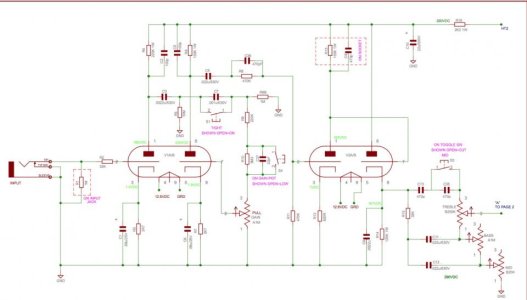
I just finished building a head based on a Marshall. I have a question regarding the schematic and what a certain part of the circuit does
What is the purpose of C1/R3 and C6/R7 coming out of the V1 and V2 Cathodes?
Is the resistor added with the capacitor as a low pass filter?
If so why are they in each stage of the V1 A & B, V2 B, but not V2 A? Is this because we have Miller Capacitance?View attachment 80257
 

Attachments

  • Screen Shot 2017-05-04 at 12.55.04 AM.jpg
    Screen Shot 2017-05-04 at 12.55.04 AM.jpg
    45.4 KB · Views: 0
Re: Help with schematic.

First off, I know just enough to be dangerous but I'll see if I can give you a start. The cathode resistor sets the bias. The bypass cap adjusts frequency response and gain. For some reason, I cant see your schematic but in a plexi I think a cap bypassing the cathode resistor on that half of V2 would mess up the frequency response of the tone stack. I very well could be wrong on that though.

Do a search for Uncle Doug on You Tube. He has some pretty good videos on tube amp tech. basics.
 
Re: Help with schematic.

Thanks for the reply. I was previously looking at some of Doug's videos, but couldn't pin down what I was looking for.
I found some documentation that is clearing it up for me.
"The guitar signal enters through the input jack and goes directly into V1 via R1/R2. The response of this stage is shaped by the combinations of R4/C2 (Plate) and C1/R3 (cathode). R4 (now 220K) sets the “load” on the tube and has an effect on the gain. C2 creates a slight high end rolloff. C1/R3 also affects the gain but more importantly, the low frequency cutoff. C1 has a dramatic effect on how tight (or loose) the amp will feel. Leaving the resistor at 2.7K, decreasing the value of C1 will move the cutoff frequency up for a tighter, but thinner, sound. Increasing C1 will move the frequency down creating more low frequency gain for a fuller sound. Too large a value here can cause the tone to get “muddy”. Notice the same values are used in the next stage cathode (R7/C5). The same scenario here. Adjusting the values in the different stages will have varying effects so try both separately to hear the individual changes."

Here, play with this. Use a cathode bypass cap value (Ck) of .00001 to simulate no bypass cap. ... https://www.ampbooks.com/mobile/amplifier-calculators/cathode-capacitor/calculator/
 
Last edited:
Back
Top