Installing basslines

bassmaniac

New member
Does anyone know how i have to install the basslines Blackouts with the blackouts 2 band eq.
I left the master tone pot out and put a on/on switch in it to kill the signal.
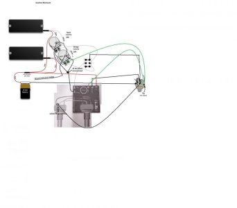
My Blackout setup on my bass.jpg
in the drawing above is a little schematic how i installed everything.
hope that you guys can help me out.
in the lower photo is the wiring diagram from the 2 band eq
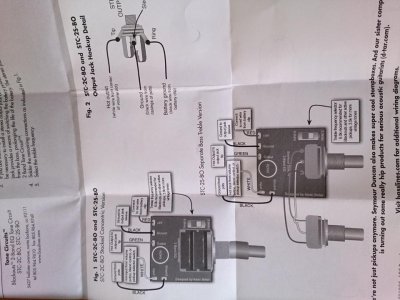
2013-06-22 17.35.09.jpg
 
Last edited:
Re: Installing basslines

The green cable connecting the volume pot and jack socket is redundant. It duplicates the signal path made by the the white output cable, DPDT switch and black output cable.

You have created in problem inasmuchas the two output signal paths run in parallel with each other all the time. When the EQ is switched into circuit, whatever corrections you dial in will be operating in parallel with the direct, unequalised signal on the first green cable. This will reduce the contribution of the onboard EQ and could create some strange comb filtering audio artefacts. (Perhaps, this is what you desire?)

If you require the EQ to be switchable, its output should return to the DPDT on/on switch rather than pass to the jack socket.

In my opinion, it is infinitely simpler to stick with the standard installation instructions. Remove the EQ from circuit by zeroing the pots to their centre detents. I set the upper band to "old fashioned" mode and tend to leave it slightly dialled in all the time.
 
Re: Installing basslines

What do you mean with dpdt because my technical english is not the best but i also so at the supportlink this option at wiring diagrams with a 3band eq and 2 volumes and then i see that the solderlugs aren't soldert to the pot.
and i have the killswitch because i don't have a master volume so i don't have to turn the 2 volumes down
 
Re: Installing basslines

DPDT is the common abbreviation for Double Pole, Double Throw - the type of switch that you are using in your diagram.

Right now, I am at work, posting via my iPhone. The screen cannot zoom into your diagram closely enough for me to re-check it. Sorry. I'll try again Saturday morning.
 
Re: Installing basslines

I have had another think about your diagram. In my opinion, there is far too much redundancy built into your circuit. You can get all of the functionality that you require by connecting things in a simple, sequential fashion.

1) Pickups to individual volume pots, outputs linked like a Fender Jazz Bass.
2) Combined pickup output to EQ PCB input.
3) EQ PCB output to Kill Switch.
4) Kill Switch to output jack.
 
Re: Installing basslines

Hey Funk fingers,
i solved the problem about the instand feedback and i rewired everything a little bit i took away the green cable from the pots to jack tip and soldered the output from volume pots to input of the pcb and took the output of the pcb to the killswitch and from there to the jack tip.
but now when i put my bridge volume down my neck volume also quits do i have to remove the cable from the solder lugs wich combines the 2 volume pots?
 
Re: Installing basslines

The way in which the volume pot terminals are wired is supposed to keep them independent. The point where they meet at the Kill Switch defeats this independent wiring.

The signals from the two pickups should pass to the PCB on a single wire, connected to the same "outside" terminal of the bridge PU volume pot that is linked to the neck PU volume pot.
 
Back
Top