You are using an out of date browser. It may not display this or other websites correctly.
You should upgrade or use an alternative browser.
You should upgrade or use an alternative browser.
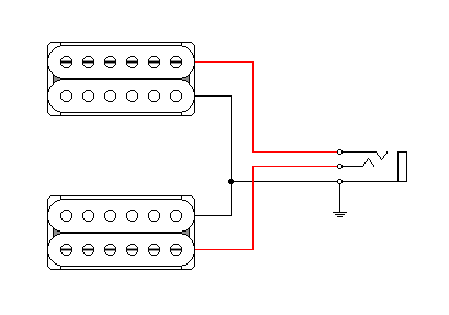
Is this schematic functional?
- Thread starter orpheo
- Start date
DavidRavenMoon
New member
Re: Is this schematic functional?
Did you check how your switch works? The terminals aren’t always the same on every brand of switch.
I haven’t looked through the diagram
Sent from my iPhone using Tapatalk
Did you check how your switch works? The terminals aren’t always the same on every brand of switch.
I haven’t looked through the diagram
Sent from my iPhone using Tapatalk
beaubrummels
Well-known member
Re: Is this schematic functional?
Position 4 doesn't look like it gets out of phase to me - only in series like position 2. Also, when the pickups are in series, it appears so are the volumes, so there's cumilative loading of resistance there, i think. The way to test is turn each individually then turn both together and hear how it sounds. Each should work, but both at the same time should get noticeably dark.
Position 4 doesn't look like it gets out of phase to me - only in series like position 2. Also, when the pickups are in series, it appears so are the volumes, so there's cumilative loading of resistance there, i think. The way to test is turn each individually then turn both together and hear how it sounds. Each should work, but both at the same time should get noticeably dark.
Artie
Peaveyologist
Re: Is this schematic functional?
Nope. It's definitely OOP. I just double checked it. But it is difficult to trace through.
Yup. In series or parallel, both volumes remain in the path. Not ideal, but it should function.
Position 4 doesn't look like it gets out of phase to me - only in series like position 2.
Nope. It's definitely OOP. I just double checked it. But it is difficult to trace through.
Also, when the pickups are in series, it appears so are the volumes, so there's cumilative loading of resistance there, i think.
Yup. In series or parallel, both volumes remain in the path. Not ideal, but it should function.
Re: Is this schematic functional?
yeah, I have a Schaller Megaswitch M and I translated it to work with that switch. I even used an Oak switch to try this out, same tonal results.
Did you check how your switch works? The terminals aren’t always the same on every brand of switch.
I haven’t looked through the diagram
Sent from my iPhone using Tapatalk
yeah, I have a Schaller Megaswitch M and I translated it to work with that switch. I even used an Oak switch to try this out, same tonal results.
Re: Is this schematic functional?
Allright, thanks. So, if I understand you correctly, if I turn down the neck volume or bridge volume in position 4, I should be able to cut the signal like normal? For some reason, I still don't get that thin, honkky out of phase tone I want.
I'll try this again on a new model soon. I have contemplated a 4 way, but what I want is:
* individual volume/tone pots per humbucker
* blade switch to select the pickups
* coilsplits
* out of phase
* series (both humbuckers in series, because the both in series split out of phase sounds GREAT: tried it with a slightly different wiring on another guitar and I wanted that tone again, but with individual volumes).
If someone can make me that, thanks!
Nope. It's definitely OOP. I just double checked it. But it is difficult to trace through.
Yup. In series or parallel, both volumes remain in the path. Not ideal, but it should function.
Allright, thanks. So, if I understand you correctly, if I turn down the neck volume or bridge volume in position 4, I should be able to cut the signal like normal? For some reason, I still don't get that thin, honkky out of phase tone I want.
I'll try this again on a new model soon. I have contemplated a 4 way, but what I want is:
* individual volume/tone pots per humbucker
* blade switch to select the pickups
* coilsplits
* out of phase
* series (both humbuckers in series, because the both in series split out of phase sounds GREAT: tried it with a slightly different wiring on another guitar and I wanted that tone again, but with individual volumes).
If someone can make me that, thanks!
Artie
Peaveyologist
Re: Is this schematic functional?
Let me chew on this, after I get some java in me. It's the dual vol/tone that makes it tricky.
Allright, thanks. So, if I understand you correctly, if I turn down the neck volume or bridge volume in position 4, I should be able to cut the signal like normal? For some reason, I still don't get that thin, honkky out of phase tone I want.
I'll try this again on a new model soon. I have contemplated a 4 way, but what I want is:
* individual volume/tone pots per humbucker
* blade switch to select the pickups
* coilsplits
* out of phase
* series (both humbuckers in series, because the both in series split out of phase sounds GREAT: tried it with a slightly different wiring on another guitar and I wanted that tone again, but with individual volumes).
If someone can make me that, thanks!
Let me chew on this, after I get some java in me. It's the dual vol/tone that makes it tricky.
Re: Is this schematic functional?
Unfortunately, I agree. I would preferably use a 4 way blade (bridge, parallel both, series both, neck) and a push pull pot for phase and a push pull pot for split. Would love to see how you design this
Let me chew on this, after I get some java in me. It's the dual vol/tone that makes it tricky.
Unfortunately, I agree. I would preferably use a 4 way blade (bridge, parallel both, series both, neck) and a push pull pot for phase and a push pull pot for split. Would love to see how you design this
Artie
Peaveyologist
Re: Is this schematic functional?
I'll draw you up both. One way that does what you showed first, but redone in a way that I think makes more sense. Also, (and I hate to cost you money), but it will be with a standard Superswitch. Even I have a hard time translating those Megaswitches to other than their stock configuration. (But I will look at the Megaswitch to see if I can adapt it.)
Then two, I'll do the 4-way, with pp's.
On a sidenote, could we maybe double up on this thread, and continue our PM discussion here, since I can't post a pic in a PM? I figure it shouldn't hurt since you're the OP.
Unfortunately, I agree. I would preferably use a 4 way blade (bridge, parallel both, series both, neck) and a push pull pot for phase and a push pull pot for split. Would love to see how you design this
I'll draw you up both. One way that does what you showed first, but redone in a way that I think makes more sense. Also, (and I hate to cost you money), but it will be with a standard Superswitch. Even I have a hard time translating those Megaswitches to other than their stock configuration. (But I will look at the Megaswitch to see if I can adapt it.)
Then two, I'll do the 4-way, with pp's.
On a sidenote, could we maybe double up on this thread, and continue our PM discussion here, since I can't post a pic in a PM? I figure it shouldn't hurt since you're the OP.
Re: Is this schematic functional?
sure, drop all you like here!
I can translate the Super to a Mega in a pinch, no worries. I kinda 'have' to use the Schaller mega; i have still 20 laying around and I have a super tiny switch cavity.
I'll draw you up both. One way that does what you showed first, but redone in a way that I think makes more sense. Also, (and I hate to cost you money), but it will be with a standard Superswitch. Even I have a hard time translating those Megaswitches to other than their stock configuration. (But I will look at the Megaswitch to see if I can adapt it.)
Then two, I'll do the 4-way, with pp's.
On a sidenote, could we maybe double up on this thread, and continue our PM discussion here, since I can't post a pic in a PM? I figure it shouldn't hurt since you're the OP.
sure, drop all you like here!
I can translate the Super to a Mega in a pinch, no worries. I kinda 'have' to use the Schaller mega; i have still 20 laying around and I have a super tiny switch cavity.
Artie
Peaveyologist
Re: Is this schematic functional?
I get it. I'll do it with the Mega. Just remind me which version it is.
As for my PM, picture this:

The wiring would look like this:

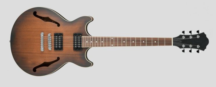
The guitar is just an example. Basically, the semi-hollow "look", with no controls, for a super clean look. If it was a quasi-semi-hollow, as you were talking about, that would be cool. All my electronics would be external.
I can translate the Super to a Mega in a pinch, no worries. I kinda 'have' to use the Schaller mega; i have still 20 laying around and I have a super tiny switch cavity.
I get it. I'll do it with the Mega. Just remind me which version it is.
As for my PM, picture this:

The wiring would look like this:

The guitar is just an example. Basically, the semi-hollow "look", with no controls, for a super clean look. If it was a quasi-semi-hollow, as you were talking about, that would be cool. All my electronics would be external.
Artie
Peaveyologist
Re: Is this schematic functional?
Cool. I'll draw it up with that. Hopefully, before the day is over.
As for the guitar, I don't even care if it's an arched top. It could also be flat top and back. Unless that would totally kill its acoustic properties. But I'd be using it electric exclusively.
Cool. I'll draw it up with that. Hopefully, before the day is over.
As for the guitar, I don't even care if it's an arched top. It could also be flat top and back. Unless that would totally kill its acoustic properties. But I'd be using it electric exclusively.
Re: Is this schematic functional?
carved is often just for looks and I personally enjoy doing it. Chambering+F-holes would be the easiest, fastest and thus, cheapest option.
Cool. I'll draw it up with that. Hopefully, before the day is over.
As for the guitar, I don't even care if it's an arched top. It could also be flat top and back. Unless that would totally kill its acoustic properties. But I'd be using it electric exclusively.
carved is often just for looks and I personally enjoy doing it. Chambering+F-holes would be the easiest, fastest and thus, cheapest option.
Similar threads
- Replies
- 3
- Views
- 109
- Replies
- 4
- Views
- 195


