You are using an out of date browser. It may not display this or other websites correctly.
You should upgrade or use an alternative browser.
You should upgrade or use an alternative browser.
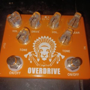
Modding a Caline/Joyo overdrive
- Thread starter solspirit
- Start date
Chistopher
malapterurus electricus tonewood instigator
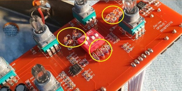
It's mostly SMT, so the easiest mod to do would be convert the internal DIP switches to external. You can also experiment with the diodes.
But thats about it.
But thats about it.
Chistopher
malapterurus electricus tonewood instigator
what dip switches?
and what JOYO is that ?
It's a KoT clone, and from the pictures I see online, it has the KoT dip switches hidden in a very inconvenient location.
solspirit
Ultimate Post Liker
It's a KoT clone, and from the pictures I see online, it has the KoT dip switches hidden in a very inconvenient location.
I did see. Someone mentioning some difficulty To get to certain components.
idsnowdog
Imperator of Indignation
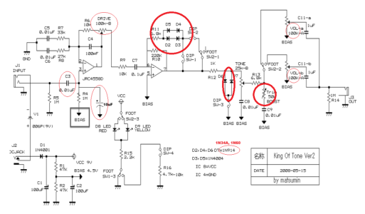
I see that the clipping diodes are through hole components but most others are SMD. So, I'm not sure how feasible any mods are. I see some value choices that I don't care for but that's my preference and not right/wrong. Going left to right in the schematic the first thing I see is a .01uF input capacitor. 90% of your frequency range is determined by your input capacitor. Large values like .1uF let more bass into the circuit. .01 is fairly bright and they chose it because they wanted the circuit to be bright and tight sounding. When combined with lower gain levels it makes the circuit sound "transparent" because only the highs are effected.
The next thing is the 1M resistor off pin 3 of the first op amp. 1M is fine if you want a clean and tight gain stage. If you want more gain you could lower that to 750K or 500K. That will give you a wider gain range and more warmth. There's no bypass capacitor for that resistor either. If you added a 10-20uF electrolytic capacitor there you could get a frequency/gain boost. The larger the value the more bass you get and smaller values have more treble.
The drive pot is 100K which is a very standard value for pedal builders. A 250K would give a wider gain range. The clipping diodes are 1N914 and 1N4004 which are silicon diodes. They are fine but they emphasize initial attack and treble frequencies. The Klon and MXR Distortion + use Germanium diodes which are darker, warmer, and more compressed. They also clip at a lower voltage so they can turn to mush if pushed hard. The two diodes in one direction and two in the opposite direction at the top is a soft clipping circuit like a Tube Screamer uses. Generally when you see the same number and type of clipping diodes in each direction that's symmetric clipping. That means the top and bottom of the waveform clip with the same shape and voltages in either direction. This gives a smooth distortion but it can sound too polite. However, if their legend is correct this circuit uses both the 1N4004 and 1N914 together. So while it looks symmetric it is actually asymmetric due to the different types. Mixing types like that can give the clipping an edgy character.
The next clipping circuit is a symmetric hard clipper to ground after the output of the second op-amp. A hard clipper creates harder clipping of the waveform at the cost of a slight loss of output . Lots of pedals use this. The waveform is squared off instead of rounded like a soft clipper. Next there's a 50K trimmer to set the boost level. You could adjust that to see how wide its range is. Lastly you have two 100K volume pots. 250K or larger would give you more volume, distortion, and wider tonal range. 100K is a very standard value but way too constipated for my tastes. Mounting the DIP switches internally mat be more durable but it is like putting your cars gear shift and turn signals in the trunk. Not a good design.
Attachments
Last edited:
idsnowdog
Imperator of Indignation
I would get some Germanium diodes and alligator clips. Attach the diodes to the clipping diodes with their bands matching the originals. That will give you an idea if you want to replace any of them. Although deciphering which diodes do what according to the dip switch settings will take a while.
Attachments
Last edited:
idsnowdog
Imperator of Indignation
I was just looking at the Joyo King of Kings
I would think the dip switches would probably correspond with the four switches on the face of the KoK
I just saw the Chase Bliss Brothers AM
Just get that
Or the Joyo
The Joyo is the same circuit but with the switches on the face. I doubt any of the component values or tone is different.
Chistopher
malapterurus electricus tonewood instigator
I saw the new Chase Bliss KoT clone too. It looks very cool and apparently they worked alongside Analog Mike on it.
hamerfan
Well-known member
This is a symmetric construction with the same Vf on both sides. The 1N4004 has the least leakage of all diodes in order to maintain clean feedback loop. It's a superior way to create a loop.However, if their legend is correct this circuit uses both the 1N4004 and 1N914 together. So while it looks symmetric it is actually asymmetric due to the different types. Mixing types like that can give the clipping an edgy character.
Chistopher
malapterurus electricus tonewood instigator
How is it superior and in contrast to what?
hamerfan
Well-known member
How is it superior and in contrast to what?
Do you know what the leakage of diode means?