My first EMG wiring - need help with a wiring diagram

alexreinhold

New member
Hey all, I have a complex wiring diagram but easy questions (at least I hope so).
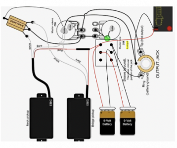
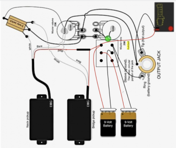
Wiring Diagram.png
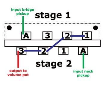
Question 1: the current illustration is for a three-way toggle switch. However, I have a three-way blade switch (like below). Can anyone translate the above to this? (i.e. where do white neck, white, bridge, volume pot and volume ground go?)
Picture 1.png
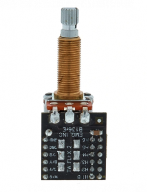
Question 2: the diagram above assumes a lot of soldering but EMGs come with the below device for connecting. Would you use it and go hybrid or cut and solder instead?
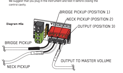
Screenshot by Snip My at 11. Mar 2022 at 10:00:24.png

As always, thank you so much for the kind help!
 
Well, if you can just simply "plug'n'play" with the EMG harness, why bother soldering a whole lot more than needed?

Also, if I understand right, you are looking to switch between 9 V and 18 V... After wiring up the switch double, better yet, triple check your wiring with a multimeter. I once managed to supply reverse current to a set of EMGs when trying to do this mod and the moment I plugged my cable in, the preamp got fried in both of them, rendering them into a nice "vintage output passive" set :D:D:D:D:D:D:D
 
Damn, you are scaring me nexion218 :2: From what I understand (please note, I'm a newbie), going series/parallel on the push pull shouldn't cause problems per se, right? Only accidental wrong wiring would, correct?

Well, rather than going normal, I had the "great" idea to come up with a combination of push/pull for the 18V mod and a low-battery indicator. I am also using an EMG push/pull which is designed for solderless. From what I see, I need to at least find ways to connect/solder:

- battery indicator wires to push/pull
- wires coming from batteries (I have a wired Warmoth battery box) to push/pull

Also, I'm still in the dark about the wiring to my 3-way blade switch :confused:
 
3 way blade gets wired as shown below.

The "A" contacts are the common input or output contacts, which are connected to one of the other contacts in each positioposition"1", "2", and "3" contacts are the contacts connected to the "A" contacts in each of the three switch positions. By convention "1' is the bridge, pickup only, "2" bridge and neck and "3" neck only.

origin.jpg
 
Awesome guys - thanks so much!!!

One last questions, can I cut the fancy "plug/play" cables by EMG on one end to solder?
 
I would leave the cables alone and tuck any excess into the cavities somehow (a) to avoid messing them up (b) so you don't invalidate your warranty and (c) in case you decide to sell them on.
 
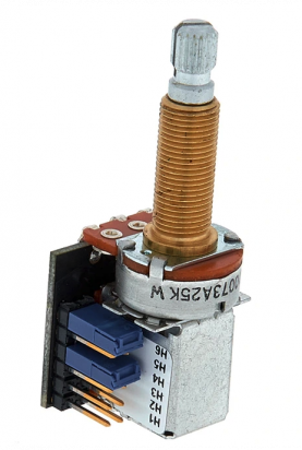
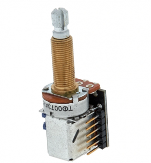
Fully agreed. But then, how do I go about it the other way? I have normal wires coming from the batteries and the low-battery indicator which have to be connected to the EMG Push/Pull Pot. However, it looks like this:

Screenshot by Snip My at 11. Mar 2022 at 15:03:57.png Screenshot by Snip My at 11. Mar 2022 at 15:03:40.png Screenshot by Snip My at 11. Mar 2022 at 15:03:12.png
 
Last edited:
I've been thinking about the issue of combining soldering and solderless a lot and here's what I want to do (incl. some of questions). It would be great if you guys can give some expert advice!

As a reminder, here's my own Wiring diagram again:

Screenshot by Snip My at 12. Mar 2022 at 09:28:28.png

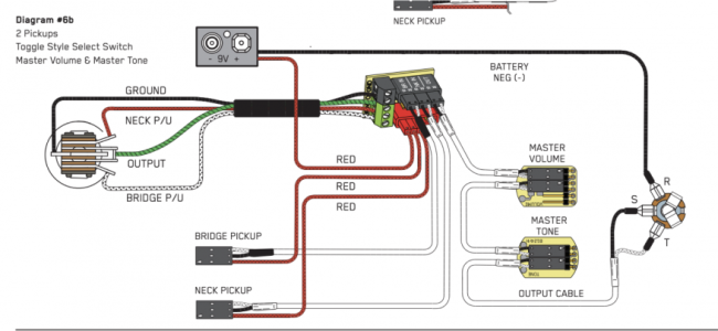
and here's the standard wiring from EMG:

Screenshot by Snip My at 12. Mar 2022 at 09:30:35.png

As you can see, one of the main differences is the buss connector EMG uses. Here's what I think:

General Remarks:
- keep the EMG solderless volume pot
- toss the complex solderless EMG push/pull pot and get a solder push/pull from Fishman or Allparts (25k of course).

For the pickups:
- keep connection to switch through buss as is
- cut red wire and connect to Fishman/Allparts push pull.

For the volume pot:
- keep connection to switch through buss as is
- keep EMG wire that is supposed to go to the tone control solderless, cut it and connect the white end (i/o) to the Fishman/Allparts push pull. Tape off the black end (ground)

General Questions:
- do i need to any grounding on my 3-way blade switch (see above, not using toggle but blade)?
- will the solderless Fishman/Allparts push/pull need a cap?

Sorry for the complexity... am really biting my teeth on this one.
 
Its not clear to me what the purpose of the push-pull control is. Are your EMG pickups splitable? If so, it will be much simpler if you retain the solderless EMG push-pull control.
 
In that case you would be better off with a normal Push-pull pot - if you can buy one in 25k value needed. The solderless one from EMG is designed for coil split of TW series pickup, so you would need to completely disassemble/destroy it to re-purpose it for your application.
 
Back
Top