Need a wiring diagram for a PG and a Filtertron

Sheiffer

New member
Hello, hope everyone here is doing well.

I'm really new to the wiring schemes, and I hope someone here can help me...

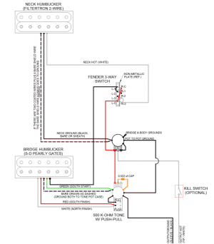
I need a wiring diagram to solder a Seymour Duncan Pearly Gate (4 wires, bridge) and a Filtertron (2 wires, neck). Each pickup will have its own volume and it will be working with a 3-way switch, on a telecaster.

The problem is, I'll use no tone, I want each pickup with a dedicated volume, plus the bridge one will be a push-pull.
​​
*edit* I forgot to mention that there will be a killswitch for both pickups.

Since english isn't my mother language I hope someone can drawn it for me, and sorry for any wrong words.


Thank you all for the help.
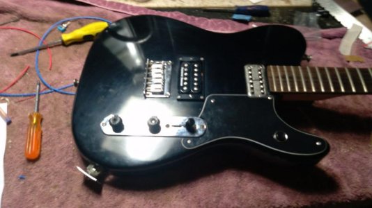
Hope this 2 pickups works well togheter.
 
Last edited:
Let's get this straight.

Telecaster type
Pearly Gates in the bridge, 4 wire humbucker
Filtertron in the neck, 2 wire humbucker
2 volumes, no tone
Push pull wanted
Kill switch wanted

Questions:

1. Push pull does what - coil split or kill switch?
2. Second push-pull for kill switch or a dedicated switch?
3. Straightforward 3-way switch or a 4-way?

Oh sorry about to many explaneition and missing info...

1- push pull splits the PG in the bridge.
2- Dedicated killswitch
3- 3-way switch.

Thanks.
 
This should work.

The Filtertron is in the neck, the PG in the bridge. A standard Tele 3-way, 1 volume and 1 tone is assumed.

The push-pull will have to go in the tone pot position. On a lot of Tele bodies, there is a reinforcing step in the bottom of the control cavity, right under the volume pot location, making the cavity too shallow for a standard push-pull (either the CTS type with the plastic casing or the smaller Fleor type). BTDT.

It is possible you could use a Gibson ($25) push-pull in the volume position to work as the kill switch. Gibson push-pulls are simple on/off types and shallower than the cheaper models. I haven't tried it so I don't know for sure. Otherwise you'll need to mount a mini switch in between the two pot knobs, drilling a hole in the control plate to accommodate it.

The push-pull is shown to coil split the bridge humbucker. As drawn it coil splits to the north (slug) coil. This may or may not give hum canceling in P2, depending on the polarity of the neck Filtertron (see below). Coil splitting to the south (screw) coil is possible as well, but the wiring is different. Let me know.

I am suggesting 500k pots and a 0.022 uF tone capacitor for humbuckers. Your choice, however.

Filtertron Wiring:

I'm not familiar with Filtertrons, but I'm assuming they're similar to 2-wire Seth Lovers. You will either have:

1. a hot (usually white) insulated wire and a non-coated braided metal sheath which acts as the ground;
or
2, a plastic sheathed main wire, which when opened up, has a white insulated wire (the hot) and multi-strand uncoated shielding (which acts as the ground);
or
3. separate insulated white (hot) and black (ground) wires plus a sheath, either plastic or braided metal.

Because of all this, and because the bare wires or metal sheath will be the ground, and may, or may not, also act as the baseplate ground, I recommend you stick to white = hot, anything else = ground.


Pickup Polarities:

Humbuckers, like single coils, have a polarity. Seymour Duncans are wired "south up" (single coils) or "south equals screw" (humbuckers) so the screw coil is the south and the slug coil is the north. The "points north" end of a map reading compass needle will point to the south (screw) coil. The planet Earth's Geographic North Pole is actually near to its Magnetic South Pole).

You may find that the Filtertron is reverse polarity (and therefore reverse wired) compared to the Seymour Duncan. You will be able to tell this is the case with a map reading compass and or because the sound in P2 - neck and bridge in parallel - will be thin and weak.

If that is the case, you can reverse the black and green (but not the bare) wire connections of the SD humbucker. It will now coil split to the south (screw) coil.


Tele Style Filtertron Humbucker Coil Split and Kill Switch.png
 

Attachments

  • Tele Style Filtertron Humbucker Coil Split and Kill Switch.png
    Tele Style Filtertron Humbucker Coil Split and Kill Switch.png
    223.2 KB · Views: 0
This should work.

The Filtertron is in the neck, the PG in the bridge. A standard Tele 3-way, 1 volume and 1 tone is assumed.

The push-pull will have to go in the tone pot position. On a lot of Tele bodies, there is a reinforcing step in the bottom of the control cavity, right under the volume pot location, making the cavity too shallow for a standard push-pull (either the CTS type with the plastic casing or the smaller Fleor type). BTDT.

It is possible you could use a Gibson ($25) push-pull in the volume position to work as the kill switch. Gibson push-pulls are simple on/off types and shallower than the cheaper models. I haven't tried it so I don't know for sure. Otherwise you'll need to mount a mini switch in between the two pot knobs, drilling a hole in the control plate to accommodate it.

The push-pull is shown to coil split the bridge humbucker. As drawn it coil splits to the north (slug) coil. This may or may not give hum canceling in P2, depending on the polarity of the neck Filtertron (see below). Coil splitting to the south (screw) coil is possible as well, but the wiring is different. Let me know.

I am suggesting 500k pots and a 0.022 uF tone capacitor for humbuckers. Your choice, however.

Filtertron Wiring:

I'm not familiar with Filtertrons, but I'm assuming they're similar to 2-wire Seth Lovers. You will either have:

1. a hot (usually white) insulated wire and a non-coated braided metal sheath which acts as the ground;
or
2, a plastic sheathed main wire, which when opened up, has a white insulated wire (the hot) and multi-strand uncoated shielding (which acts as the ground);
or
3. separate insulated white (hot) and black (ground) wires plus a sheath, either plastic or braided metal.

Because of all this, and because the bare wires or metal sheath will be the ground, and may, or may not, also act as the baseplate ground, I recommend you stick to white = hot, anything else = ground.


Pickup Polarities:

Humbuckers, like single coils, have a polarity. Seymour Duncans are wired "south up" (single coils) or "south equals screw" (humbuckers) so the screw coil is the south and the slug coil is the north. The "points north" end of a map reading compass needle will point to the south (screw) coil. The planet Earth's Geographic North Pole is actually near to its Magnetic South Pole).

You may find that the Filtertron is reverse polarity (and therefore reverse wired) compared to the Seymour Duncan. You will be able to tell this is the case with a map reading compass and or because the sound in P2 - neck and bridge in parallel - will be thin and weak.

If that is the case, you can reverse the black and green (but not the bare) wire connections of the SD humbucker. It will now coil split to the south (screw) coil.


Will this work as a 2 volumes, one for each pickup?
The guitar is "ready" bur the eletronic got messed....

Anyways, thaks for the help!
 

Attachments

  • photo105240.jpg
    photo105240.jpg
    57.7 KB · Views: 0
The push-pull part will, but you should wire the rest like this.

To get independent volumes you can swap the "in" and "out" wires on the pots over. You may also need to ground each pot's third lug directly to the output jack and delete the pot to pot ground.. I don't know why but volume pot to volume pot grounds seem to defeat the independent volume functionality.

Tele_2S_3B_2V.jpg
 
Qell, thanks, but I still dont get it, should I use one part from 1 scheme and the other part from the other scheme? I think this is the opposite to simple. But I gess Im missing something, anyway thanks, but I'll keep searching, as I said, Im noob to it.
 
Your wiring isn't 'standard', therefore it's not going to be entirely simple. If you are going to wire a guitar with customizations, it might be worth starting to learn how to read a schematic or wiring diagram at least.

2NsDJSA.png
 
Your wiring isn't 'standard', therefore it's not going to be entirely simple. If you are going to wire a guitar with customizations, it might be worth starting to learn how to read a schematic or wiring diagram at least.

Hey beau; Love your diagrams, but that's not a good way to do a kill switch. You're breaking the "hot" line, which will leave the input to the amp floating. You'll probably pickup up all kinds of hum, buzz, and RF noise. A killswitch should really be wired to just short out the two terminals of the output jack. IMHO.
 
Hey beau; Love your diagrams, but that's not a good way to do a kill switch. You're breaking the "hot" line, which will leave the input to the amp floating. You'll probably pickup up all kinds of hum, buzz, and RF noise. A killswitch should really be wired to just short out the two terminals of the output jack. IMHO.

Fair. Didn't think it would matter if it's inside the guitar, but I don't use kill switches. I can fix it. Like this?

9QPqk4T.png
 
Last edited:
Fair. Didn't think it would matter if it's inside the guitar, but I don't use kill switches. I can fix it. Like this?

Definitely better. A smidgen more complex than it needs to be, but better. You only need the killswitch to short out the output jack.
 
Definitely better. A smidgen more complex than it needs to be, but better. You only need the killswitch to short out the output jack.

I thought that's what it is doing? Unless you mean to put the pickup selector switch output to the center lug of the killswitch with the jack hot wire? Isn't it electronically the same now? His guitar has the kill switch on the lower horn of the pickguard. I was trying to find a way to do it with the nearest wires.
 
I thought that's what it is doing? Unless you mean to put the pickup selector switch output to the center lug of the killswitch with the jack hot wire? Isn't it electronically the same now? His guitar has the kill switch on the lower horn of the pickguard. I was trying to find a way to do it with the nearest wires.

I'm probably being too anal about this. :p

I did this quik-'n-dirty using your diagram:

beau_killswitch.png
 
I'm probably being too anal about this. :p

I did this quik-'n-dirty using your diagram:


Yeah ok. When the switch is on kill, that looks electronically the same to me. But with this latest scheme he has to run two more wires from the jack all the way to the treble side horn on the guitar. I was trying to keep it leaner and use the nearest connections.
 
When the switch is on kill, that looks electronically the same to me.

It's only subtly different. That connection can be anywhere as long as it's between hot and ground. What I was getting at is to not break the hot connection. Even for that millisecond when the switch travels from one contact to the other, you can get a loud pop. By doing it 2-terminal, it won't. The switch can be physically where you had it.
 
It's only subtly different. That connection can be anywhere as long as it's between hot and ground. What I was getting at is to not break the hot connection. Even for that millisecond when the switch travels from one contact to the other, you can get a loud pop. By doing it 2-terminal, it won't. The switch can be physically where you had it.

If you get a pop, I think you can just add an inline resistor to avoid it. I seem to recall the Gibson Varitone circuit used one at a particular point in the circuit for the same reason. But ok, you win. :beerchug:
 
WhatsApp Image 2022-03-09 at 17.05.58 (1).jpg - Click image for larger version  Name:	WhatsApp Image 2022-03-09 at 17.05.58 (1).jpg Views:	0 Size:	48.2 KB ID:	6156843
I'm probably being too anal about this. :p

I did this quik-'n-dirty using your diagram:


Hi all,
After some telling me to study I started to learn how to solder, until now I just asked for schemes to pay someone to solder for me.

Well I made the wiring scheme above, its my first time soldering so ignore the ugly things.
​​​​​
I learned a hard lesson today, there are diferents types of switches, and mine isn't equal the schene one...

=(

Tomorrow I'll try to tanslate the scheme to my alpha switch, and if works solder the pickups, any help is welcome.
 
Last edited:
Back
Top