Need to understand how parallel and series wiring works on a 4way

thornev

New member
My post title doesn't really say what I want. I understand parallel and series wiring. What I don't understand is how the attached 4-way blade switch wiring implements parallel and series effects.

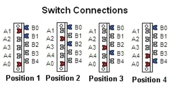
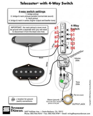
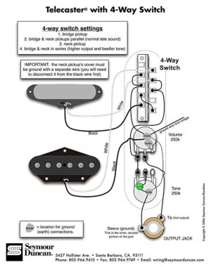
Let me be clear - I am NOT looking for wiring diagrams. There are thousands of those that I've studied. The knowledge I'm trying to achieve is to understand how the wiring of the attached switch implements parallel and series between Telecaster pickups. In other words, given the attached wiring diagram, when the 4-way blade switch is in positions 2 and 4, which lugs are active and how is it that those active lugs can produce the parallel and series effects? I've studied and studied that diagram and I know how to wire 2 pickups outside a guitar in parallel and series, but I can't understand how those effects are achieved by the way this blade switch is wired. So if someone can explain it so a 10th grader (which I'm not) can understand it, I'd really appreciate it.
 

Attachments

  • tele_4ws-809x1024.jpg
    tele_4ws-809x1024.jpg
    55.7 KB · Views: 0
Last edited:
The sd diagram lays out the lugs of the switch kinda weird. This might help.
swl4connections__91953.jpg Screenshot_20240212_160457_Chrome.jpg
 

Attachments

  • swl4connections__91953.jpg
    swl4connections__91953.jpg
    54.2 KB · Views: 0
  • Screenshot_20240212_160457_Chrome.jpg
    Screenshot_20240212_160457_Chrome.jpg
    50.7 KB · Views: 0
Thanks, hw. I have seen that diagram. I've observed that different switches number the lugs differently which adds to my confusion. Assuming the diagram you posted represents how the SD switch I posted works in the switch positions, I still need to understand how the wiring implements parallel and series. I know that parallel means outputting the + leads together and the "-" leads together, and series means outputting the start (+) of one coil and the finish (-) of the other coil and the "-" of the first coil is connected to the "+" of the other coil. But I just don't get how the wiring I posted implements it.
 
One thing to keep in mind is that the black lead (-) of the bridge is going to ground, and the white lead (+) of the neck is going to the vol pot in. Both are true regardless of whichever position the switch is in.

In pos 4, lugs a0 and a4 are connected, as well as b0 and b4. The wiring implements a jumper from a4 to b4, so the black (-) of the neck goes to the white (+) of the bridge pup, so series wiring is achieved.

In pos 2, lugs a0 and a2 are connected, as well as b0 and b2. A2 has a jumper going to a3, which goes to ground, so the black (-) of the neck gets grounded, and the white (+) of the bridge goes to the vol pot in, so both pickups are output independently, ala parallel.

Hope that makes sense.
 
Aha ! I mislabeled the lugs. I had them going from top to bottom on left, A0 to A4, and on the right from B1 to B0. OK, now that that's corrected in my head, your description of position 4 makes a lot of sense.

Position 2 is still a mystery to me. How does B2 get activated if common A0 is not connected to common B0 which would be required in order for a blade to activate the same lug numbers on both poles A and B? Also B2 is not activated because it is not connected to B0. Is B2 active because it always has the neck "+" signal via B1?

I'll study more later. I have wifey duty right now.
 
Don't think of the common lugs(a0, b0) as outputs, or "active" lugs. It's lugs a2, a3 (going to ground) and b1, b2 (going to vol pot in) that are actually going out from the switch, regardless of whether or not they make connections with the common lugs, because they are directly connected to the back of the vol pot, and vol pot in, respectively.
 
So it's not just bridge "-" going to ground that is always active. A2 and A3 are always active too?

And it's not just neck "+" going to VOL out that's always active. B1 and B2 are also always active?

Or is it that A2 and A3, and B1 and B2 become active only when a switch position blade touches one of them?
 
That is correct. A2 and A3 are always connected to ground, and B1 and B2 are always connected to the vol pot in. It doesn't matter what position the switch is in.

So in pos 2 the neck (-) in A0 will make contact with A2 so it gets sent to ground. The bridge (+) in B0 will make contact with B2 so it goes to the vol pot in.
 
This is a revelation, thank you, hw. So is it safe to deduce that a blade wiring diagram where any of the lugs are connected directly or indirectly to ground or to VOL pot output that those pickup connections will always be active regardless of blade position? If so, then I guess it's a matter of seeing if the blade position activates any additional pickup leads in order to see if polarity, phase, parallel or series configurations are active?

UPDATE: I understand that in the diagram in my original post, B1 and B2 go actually to the VOL IN lug and VOL OUT is the middle lug.
 
Last edited:
That is correct. If a switch lug is wired directly to another point the switch can have no effect on that lugs direct connection. Any connection for that matter, if it's directly connected to something, with nothing in between, that connection cannot be disrupted,

Yes, b1 and b2 are wired directly to the vol pot in (1st lug).
 
Great. How is it down there in good ol' TX? I lived in Austin (actually unincorporated Round Rock, Williamson County) for 9 years. Loved it. Didn't want to leave but had to for family reasons. I had such a ball each year at SXSW. I did SXSW stage production for 6 of those years at Maggie Mae's (later The Living Room). What a zoo !
 
Weather's kinda unpredictable lol but good otherwise. I guess it's a good place to live since we got so many folks moving down here!
 
Really. When I moved there it was The Great Migration because my company sent all of its FL employees to Austin. That would be 1995-ish. It was so inexpensive back then. I bought 2800 sq ft for $214,000 !! I've been told that house now goes for over $500,000 ! I should have stayed..LOL. I was there during one of the ice storms. Mopac was a parking lot of fender benders !
 
I think you have this answered, but sometimes it's easier to visualize something.

Red lines just show which contacts are connected in pos #4. No actual wires.

Start at red arrow.
Current flow through blue highlight, through bridge pup to switch.
Then through switch contacts indicated by red line.
Then through yellow highlight,to switch contacts with red line.
Then through green highlight of neck pup.(Note bridge pos.to neck neg.)
Finally, through lavender highlight to volume pot. (Green arrow.)

Tele_4-way_path.png

 
Thanks, Artie. I wish I had such pictures when I started trying to figure it out. One thing... Why do we start at the red arrow which is ground? I was always starting at the pickups and trying to trace from there since the pickups are the source of the signals.
 
Simply because current flows from negative to positive. I realize that a pickup signal is AC, so I think of it as an instant moment in time. You can, of course, go the other way.
 
Current IS electron flow. Pos to neg was the "old" way of thinking before they understood electron flow. They had a 50/50 chance of guessing right. they got it wrong.
 
Back
Top