No Jumper when splitting stack pickups??

Astrojam

New member
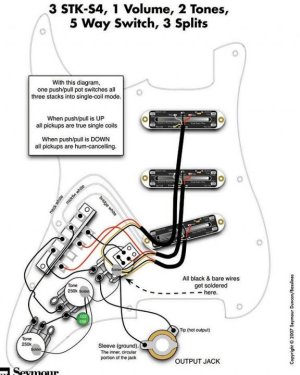
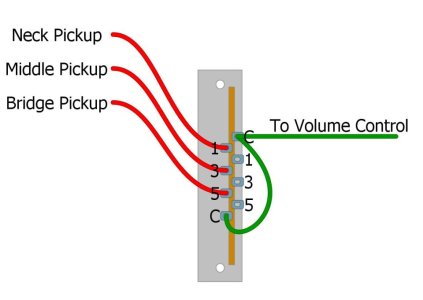
Hey quick question I think. Could someone please explain why in these two diagrams the usual jumper wire from a0 to B0 is omitted. It seems like once a push pull split is added, that wire gets removed?

just trying to track down why I’m losing bridge and neck when splitting coils.

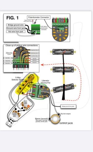
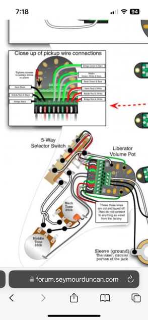
third pick is liberator wiring without a push pull split and jumper included.
 

Attachments

  • photo114380.jpg
    photo114380.jpg
    87.6 KB · Views: 0
  • photo114395.jpg
    photo114395.jpg
    47.6 KB · Views: 0
  • photo114396.png
    photo114396.png
    177.7 KB · Views: 0
Where did you find those two Liberator diagrams? I don't see them on the site. Are they included with the Liberator? Unfortunately, I've misplaced mine.

The first diagram is correct. The two Liberator diagrams have a couple mistakes, and an oddity. Both diagrams need to have leads from the two tone pots case connected to a ground pad on the Liberator. The green wire, (4th wire down), is grounded, but isn't connected to anything on the "screw" end. I suppose they did that just so it wasn't floating around and touching something it shouldn't. You could just tape it off instead.

I'm not sure which "jumper" you're referring to.
 
Hey thanks for the response on this. The diagrams came from an email from support@seymourduncan. This is also the first I found this diagram and will get it posted on the other thread as well.

I originally went down this rabbit hole trying to figure out a phasing issue when I first installed from the factory wiring. SD support was just telling me it was the classic quack sound I get from between positions but it absolutely was not. In hindsight I should have sent audio. There was a huge drop in tone and volume.

Also searching forums it looks like some pickups have been sent out that weren’t reverse wound.

Anyways. Chasing swapping leads I finally got to a place where everything works minus single coil split mode. I’m sure there’s another lead combination swap that would sort out the phase, but I’m done with that for now. Sorry for the broken record.

Good point on the leads from the tone pots Artie. . Although I think they are there just very faint gray wire.

the jumper I was referring to is in this photo going c to c terminal. Modern 5 way wiring. Thinking about it more I’m realizing it’s wired differently and probably not needed. Was thinking it would go from liberator volume to black wore from push pull to switch. But that’s probably wrong.

thanks again for the responses
 

Attachments

  • photo114403.jpg
    photo114403.jpg
    40.8 KB · Views: 0
I don't think you want a Common jumper, as that will split the pickups using the hot lead, which I believe would be the bottom coil on a stack? I think what is missing is the jumper on the push pull needs to go to ground.
 
Beau is correct. Your 2nd diagram is using auto-split. You don't want to connect the commons on the 5-way.

I think what is missing is the jumper on the push pull needs to go to ground.

It's there. Just hard to see. Tripped me up at first also.

connection.jpg
 
You don't need a jumper from the "A" side of the switch to the "B" side because the p/p is only switching the red (coil split) wire to either grounded (split) or isolated (humbucker). However, as Artie pointed out, the p/p should have the "split" terminal grounded.
 
Thanks guys for all the help. That makes so much more sense explaining the coil split like that. Last question on this then I will put it to rest.
I feel like I’m reading conflicting points on grounding. From what I can gather sounds like the pots are in fact case connected and run to the ground on liberator via the grey wires. The lead however from pp on the split side to switch is not grounded and needs to be…do I have this correct?

Thanks again. No idea I’d be learning this much about wiring.
 
That diagram is really poorly drawn, and thus confusing. (And wrong.)

The two gray flying leads, (red arrow), correspond to the two gray flying leads in the close-up, (green arrow).

The push-pull is soldered to the middle tone pot case.
The tone cap is soldered to the neck tone pot case.
The bridge and middle black/yellow wires are connected to the gray flying leads, which are brought down to those same points on the tone pot cases.

But neither tone pot case is actually connected to ground anywhere. That means that the bridge and middle grounds, tone cap, and push-pull are also not grounded.

So, you can simply add the blue wire I show to solve that problem.

Ideally, the two gray flying leads would connect to one of the several ground pads of the Liberator, and then add the blue wire. Both methods work, but the latter makes more sense electrically.

Corrected.jpg
 
Note: (Since I can't edit above.) The tone pots might be grounded by foil on the pickguard, but that's a terrible ground. It's meant for shielding. Not electrical grounding.
 
Back
Top