Firstly, I may have misunderstood the basics, so let's start with a Plain Coil Split
Imagine I have a Dimarzio humbucker and I have Green hot, White ground for one coil and Black hot Red ground for the other. I can see that taking the white and black to ground leaves the Green to White coil unaffected, but the Black to Red coil is shorted out as the Black (hot) is shorted to ground to the Black to Red Coil is inactivated.
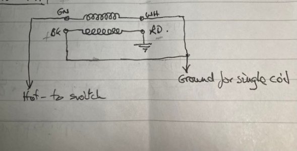
Now take a partial coil split where the white and black wires go to ground via say a 6k resistor. The idea is that the Black to Red coil isn't fully shorted out. Somehow the resistor mean that the Black to Red coil isn't totally shorted out.....as the resistor, well, resists the direct path to ground....so some current still makes it through the Black to Red coil.
Now that kind of made sense to me originally, and I've done it before. Next, I got a Dimarzio DP188, side by side single coil sized humbucker.
I had the guitar routed for it and it wired in with a push push pot....and as I expected the single coil was way too low output.
So, I tried a partial coil split. I could get the volume I liked but the single coil like sound was way too bassy.
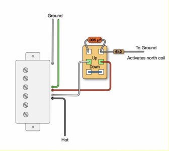
I googled and found this set up.
Different wire codes to the Dimarzio, but the idea is that the full coil goes via a capacitor to bleed through the treble frequencies, and the coil that is shunting to earth goes via a resistor to ground...to partially shunt it out.
With some experimentation I found 2nF capacitor to give me the sound I liked.
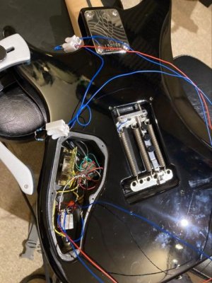
But here is where my brain starts to get twisted. The wiring job was bad with dull joints etc as my soldering iron tip broke part way through the job etc.....and I had a duff push push pot, so I got fresh stuff and decided to wire it all up again with a "test rig" - extended wires allowing me to easily clip in different value components while the guitar was still plugged into my amp.
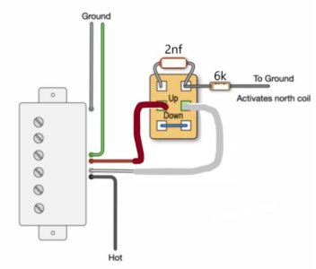
Taking the wiring apart, I realised that I had mistakenly reversed the split wires.....so I was actually pushing the shunted coil over the capacitor not the full coil.
So in my tests, I did it 'properly'. I quickly arrived at my 6k resistor being the value that worked for me. Any capacitors in circuit not only made the guitar sound weedy but also I got lots of hum.
Another effect was that the tone control stopped functioning like a tone control and acted more like a volume.
Having checked I had indeed wired everything as planned, I went back to my original mistaken wiring.
So, with the partially shunted coil going over the capacitor. No hum, tone control worked fine, got a much nicer more chimey single coil like sound.
So, here are my questions.
1. In either partial coil split, or partial coil split with capacitor (HPF), I started to wonder, why does the resistor not also drop the volume of the active coil? A volume pot is essentially a variable resistor right? So why does the resistor not also reduce the volume of the coil that is in circuit, the one that isn't being shorted out?
2. Why would putting the capacitor in series with the resistor, and acting upon the full coil (as per the diagram) have the effects it did - sounding weak, lots of hum, tone control changing function?
3. Why would putting the capacitor in series with the resistor acting on the partially shunted coil work beautifully?
A few pics that hopefully might help.
The original design, based on green ground, red hot, white ground, black hot
What I ended up with (but the wording is wrong...Activates....)
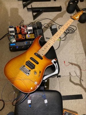
And my test rig
Thanks,
Andy
Imagine I have a Dimarzio humbucker and I have Green hot, White ground for one coil and Black hot Red ground for the other. I can see that taking the white and black to ground leaves the Green to White coil unaffected, but the Black to Red coil is shorted out as the Black (hot) is shorted to ground to the Black to Red Coil is inactivated.

Now take a partial coil split where the white and black wires go to ground via say a 6k resistor. The idea is that the Black to Red coil isn't fully shorted out. Somehow the resistor mean that the Black to Red coil isn't totally shorted out.....as the resistor, well, resists the direct path to ground....so some current still makes it through the Black to Red coil.
Now that kind of made sense to me originally, and I've done it before. Next, I got a Dimarzio DP188, side by side single coil sized humbucker.
I had the guitar routed for it and it wired in with a push push pot....and as I expected the single coil was way too low output.
So, I tried a partial coil split. I could get the volume I liked but the single coil like sound was way too bassy.
I googled and found this set up.
Different wire codes to the Dimarzio, but the idea is that the full coil goes via a capacitor to bleed through the treble frequencies, and the coil that is shunting to earth goes via a resistor to ground...to partially shunt it out.
With some experimentation I found 2nF capacitor to give me the sound I liked.
But here is where my brain starts to get twisted. The wiring job was bad with dull joints etc as my soldering iron tip broke part way through the job etc.....and I had a duff push push pot, so I got fresh stuff and decided to wire it all up again with a "test rig" - extended wires allowing me to easily clip in different value components while the guitar was still plugged into my amp.
Taking the wiring apart, I realised that I had mistakenly reversed the split wires.....so I was actually pushing the shunted coil over the capacitor not the full coil.
So in my tests, I did it 'properly'. I quickly arrived at my 6k resistor being the value that worked for me. Any capacitors in circuit not only made the guitar sound weedy but also I got lots of hum.
Another effect was that the tone control stopped functioning like a tone control and acted more like a volume.
Having checked I had indeed wired everything as planned, I went back to my original mistaken wiring.
So, with the partially shunted coil going over the capacitor. No hum, tone control worked fine, got a much nicer more chimey single coil like sound.
So, here are my questions.
1. In either partial coil split, or partial coil split with capacitor (HPF), I started to wonder, why does the resistor not also drop the volume of the active coil? A volume pot is essentially a variable resistor right? So why does the resistor not also reduce the volume of the coil that is in circuit, the one that isn't being shorted out?
2. Why would putting the capacitor in series with the resistor, and acting upon the full coil (as per the diagram) have the effects it did - sounding weak, lots of hum, tone control changing function?
3. Why would putting the capacitor in series with the resistor acting on the partially shunted coil work beautifully?
A few pics that hopefully might help.
The original design, based on green ground, red hot, white ground, black hot

What I ended up with (but the wording is wrong...Activates....)

And my test rig


Thanks,
Andy
Last edited:
