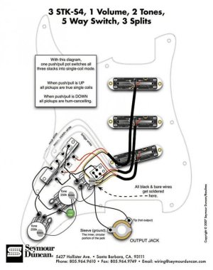
Problems with wiring STK-S4 as per SD diagram

A_Zed

New member
I have a 1977 Ibanez Strat copy that I bought as a young tacker and finally I got around to doing some work on it.

I bought new pots (2 x 250K and 1 x 250K push-pull), 5-way switch (DM-50), a .022 capacitor and three STK-S4 pickups. I followed the Seymour Duncan diagram "3 STK-S4, 1 Volume, 2 Tones, 5 Way Switch, 3 Splits" but the result I get when doing a "tap-the-pickup-with-a-screw-driver-and-plugged-into-the-amp" I only get noises from the Neck and Middle pickup.

I wish to know if anyone has had similar issues as I can't find anything searching through the forums.

Thanks in advance to anyone that can help.

AZ
 
Re: Problems with wiring STK-S4 as per SD diagram

Welcome to the forum.

Unfortunately, all 5-way switches are not created equal. Look at "A" and "D":

5-way_styles.jpg


They almost look identical, except that "A" has the common terminal on the right, (finger pointing), and "D" has the common terminal on the left. Duncan diagrams are based on the more common "D" switch. Your symptom would occur if you have the "A" switch.

Look closely at the switch and see if you can tell which you have. Did you buy it from Stew-Mac? Then we can go from there.

Artie
 
Re: Problems with wiring STK-S4 as per SD diagram

Welcome to the Seymour Duncan User Group Forum A_Zed!

The signal path for hot side of the switch is a common Strat wiring with the tone controls getting their feeds from the mid and neck hot terminals. Since you aren't getting anything from the mid and neck pickups I have to assume that you have something wired incorrectly in the tone pots that is causing the mid and neck pickups to be getting grounded out of the circuit.

I am not sure how they are working the splits because I don't see a ground source for the red wires. That shouldn't effect your humbucker mode though.

Sounds like a wiring issue to me.
 
Re: Problems with wiring STK-S4 as per SD diagram

I think its his bridge that doesn't work. :)

Pulled that from the "archives", this early Sunday morning.
 
Re: Problems with wiring STK-S4 as per SD diagram

I'm in Australia and purchased from an Aussie online guitar parts store. Looking at what you've shown, it is like "A", and looking at the Stew-Mac web site, it is exactly like #3192. Your "A" is #3191.

Thanks for replying to my post.

AZ
 
Re: Problems with wiring STK-S4 as per SD diagram

Ah . . . then its connection scheme will be different then whats shown on the Duncan site. I can do a "translation" for you, but it will take a little time. I'm right in the middle of catching up on another . . . and my wife is making "lets paint" noises. Hum-cancelling won't fix that one. :D

(Before the day's over.)
 
Re: Problems with wiring STK-S4 as per SD diagram

Thanks for that Artietoo. I await your reply in antici............................................................


...................pation.


AZ
 
Re: Problems with wiring STK-S4 as per SD diagram

As you look at the switch, from the bottom, as it would go in that diagram, I believe you'ld do this:

a-zed.png


I'm 99% sure thats correct. I hate doing these translations when I don't have the actual switch in my hand.
 
Re: Problems with wiring STK-S4 as per SD diagram

I'm at work at the moment and have just over 2 hours till knock-off. I can hardly wait to get home and try this out.

I'll post back once I've tried this out.

Thanks heaps for your help ArtieToo, it is much appreciated.
:yourock:

AZ
 
Re: Problems with wiring STK-S4 as per SD diagram

ArtieToo, I have a little query with the wiring. The SD diagram for what I want has the black and bare wires grounded. http://www.seymourduncan.com/support/wiring-diagrams/schematics.php?schematic=3stks41v2t5w3s This makes me assume that the red and white are the single coil/noise-cancelling wires.

The effect I wanted to get is with the push-pull switch being able to change it from all pups single coil or all pups noise cancel. The diagram you give me looks as if they will always be in noise-cancel mode.

Am I making sense?

It's fun being a nube at 48. Sorry.
 
Re: Problems with wiring STK-S4 as per SD diagram

Sorta . . . black and bare are ground. White is the "hot" output. Red is the splitting/noise-cancelling wire. You leave them unconnected for normal noise-cancelling. You ground them for splitting.

That diagram does what you want . . . sorta. Ironically, it has a "typo" on it and they omitted the ground connection on the push-pull. See the little short jumper on the push-pull? That also must connect to ground for this to work. Continue to use my translation of the switch, but add that ground connection.
 
Re: Problems with wiring STK-S4 as per SD diagram

As you look at the switch, from the bottom, as it would go in that diagram, I believe you'ld do this:

a-zed.png


I'm 99% sure thats correct. I hate doing these translations when I don't have the actual switch in my hand.

YES you are 100% absoultly right. Apart fro the colours that is Had exacly the same problem this afternoon it wasnt till i checked the pole outputs and came to the same conclusion as your self. Its now wired up and working great for a customer . And it also explains why the neck and mid pups were working a little and nothing else i am a guitar repairer but this was the 1st one these switches ive came across. I feel the need to tell my freind who sells them at his shop and advise him to give a diagram with each one he sells to save his customers the head scratchin and him the complaints. I am impressed by the quilty of the DM-50 switch there made very well and sturdy

Chris
 
Last edited:
Re: Problems with wiring STK-S4 as per SD diagram

with DM-50 switch.jpg
OK right IVE edited this diagram in photo shop for use with the DM-50 5 way switch this should work absolutly fine with the DM-50 5 way switch you just have to remember that on the DM-50 the outputs are oppersite to the fender based 5 way switches where the out put on fender based switches are 4th down on left side on outer pole and 1st at the top on right side inner pole . on the DM-50 the output is the the 1st at the top on the left side on the outer pole and the 4th down on the right side inner pole just remember to face the spring outwards on the scratchplate and jobs a gudun other than that they are the same beast like i said earlier I wired DM-50 only a few hours ago
So wire and injoy
Chris
 
Last edited:
Back
Top