So this happened... NPD (DIY content)

ThisDyingSoul76

New member
Was described on eBay as Fuzz Face, but clearly us not... Suspect it's an IC Muff clone.

Now if I can just figure out what I did wrong to cause no sound when on but getting the bypass sound.

Jacks, pots and LED are fine, Electrolytic Caps installed to correct polarity, no cold/bad solder...
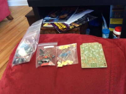
image.jpg
Only thoughts are a cap or resistor in the wrong place or something goofy with the switch (solder flowed down and bridged under the PCB?)

Arrrrgh!
 
Re: So this happened... NPD (DIY content)

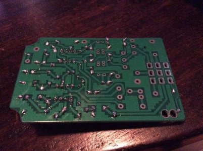
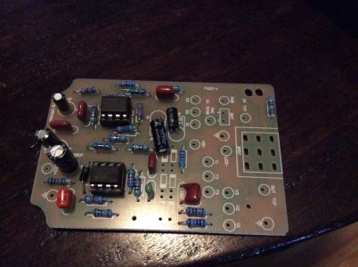
Pic is up to installing everything but the transistors, pots, jacks, power and switch and the underside at the same point. I suspect the problem lies in the progress up to this point. I can try getting more pics tomorrow after work with all the wires connected and with a closer view.
image.jpg

image.jpg
 
Re: So this happened... NPD (DIY content)

As best as I could tell, film caps are all in right spot. One was so faded I couldn't read the markings, so I left until last and paced it by process of elimination.
 
Re: So this happened... NPD (DIY content)

The underside pic is too low res to pick much. It looks as if you have stray solder on the board. Clean it off with a stiff brush. Some of the soldered points look like they might need a reflow[ resolder ].
 
Re: So this happened... NPD (DIY content)

ICs on the board whilst heat is being applied to other parts of it?
 
Re: So this happened... NPD (DIY content)

ICs on the board whilst heat is being applied to other parts of it?
IC's were the second to last piece before the wiring. Installed sockets then placed the chips in after. Area around the IC's was cool to touch while doing the wiring and the 6 transistors that are missing at the point of these pics.
 
Re: So this happened... NPD (DIY content)

The underside pic is too low res to pick much. It looks as if you have stray solder on the board. Clean it off with a stiff brush. Some of the soldered points look like they might need a reflow[ resolder ].

I'd checked that out, nothing seems to actually touch tracks that are not directly connected to the respective solder pads... But I have been wondering if some of those globs of Solder that seem rounded at the bottom should be cleaned off and redone. Perhaps they aren't making a good connection to the pads?
 
Re: So this happened... NPD (DIY content)

I'd checked that out, nothing seems to actually touch tracks that are not directly connected to the respective solder pads... But I have been wondering if some of those globs of Solder that seem rounded at the bottom should be cleaned off and redone. Perhaps they aren't making a good connection to the pads?

If you have a magnifying glass, check your solder points and around the tracks with it. You may be surprised at the solder spatter you find that way.
 
Re: So this happened... NPD (DIY content)

Bust out the multimeter! Check all your components. For all we know could be a bad cap. Also, did you check cap polarity 3x before installing? I've made that mistake a few times.
 
Re: So this happened... NPD (DIY content)

It didn't come with a schematic you can use to troubleshoot?

$15 eBay pedal from China... Seemed like a good first project based on the theory I'd avoid wasting too much money if I screwed up... But after seeing I only got a paper print out of the circuit board with the values marked for each component... Seems it may have been better to spend a bit more money. Lol

It was supposed to be a fuzz face clone... As you can see by the pics that is no fuzz face. Of what I can find out, based on the op amps that came in the kit the closest match seems to be the IC Big Muff, but I can't be sure.
 
Re: So this happened... NPD (DIY content)

Bust out the multimeter! Check all your components. For all we know could be a bad cap. Also, did you check cap polarity 3x before installing? I've made that mistake a few times.

Quadruple checked cap polarity. Going over the rest soon.
 
Re: So this happened... NPD (DIY content)

$15 eBay pedal from China... Seemed like a good first project based on the theory I'd avoid wasting too much money if I screwed up... But after seeing I only got a paper print out of the circuit board with the values marked for each component... Seems it may have been better to spend a bit more money. Lol

It was supposed to be a fuzz face clone... As you can see by the pics that is no fuzz face. Of what I can find out, based on the op amps that came in the kit the closest match seems to be the IC Big Muff, but I can't be sure.
Yeah definitely looks like an op amp big muff. I'm sure they copied a layout, maybe a schematic online matches?
 
Back
Top