Switch for series/parallel 2 humbuckers

Hi all.

I'm about to undertake this mod myself and just wanted to clarify.
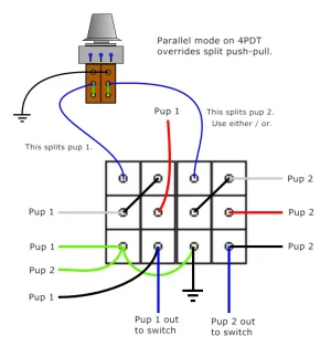
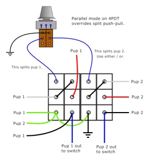
From the image posted the only two wires leaving the 4dpt switch would be the black and ground? Ground going to back of the volume pot and black going to the 3 way selector switch in the standard way you would wire up 2 humbuckers to a 3 way switch.

Cheers!
 

Attachments

  • 73359-0d864eab458fa7a7d01a6aa4913e351d.webp
    73359-0d864eab458fa7a7d01a6aa4913e351d.webp
    12.7 KB · Views: 16
Three wires. One common ground, and the two "hot" wires. (Blacks, shown in blue, leaving the switch.) Like this:
 

Attachments

  • 4PDT-switch 2.webp
    4PDT-switch 2.webp
    14 KB · Views: 13
It's important to note, for anyone else following this post, that wiring is only for a 4PDT on-on switch for series/parallel.

If you want a 4PDT on-on-on switch, for series/split/parallel, it might change depending on where you obtain the switch. There are two different styles of 4PDT on-on-on switches. 4PDT on-on switches are all the same.
 
Reporting in to say i wired it up today and it worked perfectly.
Albeit fiddly as hell but with some patience i got it working first try. 🤘
 
I also like to leave just enough wire, and dress it properly, so that after it's all wired up, and I go dang . . . I wanted series to be the down position, I can just rotate the switch 180 in its hole.
 
Say I wanted to add a coil split option in the future with a push pull pot without changing the existing 4pdt switch that has the functionality of series/parallel. How would this differ from my existing wiring?

I have a 500k push pull pot laying around so i know ill be tempted at some point haha.
 
Like this. Separate push-pulls can be used for independent splitting.
 

Attachments

  • 4PDT-switch 3.webp
    4PDT-switch 3.webp
    26.2 KB · Views: 7
Like this. Separate push-pulls can be used for independent splitting.
Thanks Artie, you seem to be a wizard at this stuff so i couldn't pass the opportunity to ask.

Can i just clarify. The top 2 lugs go to ground, the middle 2 lugs are receiving output from the 4dtp switch designated by the 2 separate blue wires and the bottom 2 lugs are receiving 2 jumper wires from the middle lugs of the push/pull pot?
 
Last edited:
Almost. Not quite. No jumpers. Those green lines indicate the internal position of the contacts when the push-pull is down. I stole that snippet from one of my other drawings showing how a push-pull, or push-push works. You would only use the ground wires and the blue lines.
 

Attachments

  • push-pull.webp
    push-pull.webp
    6.5 KB · Views: 8
artie, you are a gem bro. love how often you jump in and whip up a visually pleasing diagram. i can wire things, but my skills at making a schematic that someone can read are severely limited.
 
Thanks Jeremy. One of the things I love about my paint program is, it lets me store images as "stamps." So many things I just "stamp", as a stamp pad, and not redraw them from scratch. Helps to make some things quick, now that I've been using that software for 30-something years.
 
Almost. Not quite. No jumpers. Those green lines indicate the internal position of the contacts when the push-pull is down. I stole that snippet from one of my other drawings showing how a push-pull, or push-push works. You would only use the ground wires and the blue lines.
Ah i see! Thanks so much for clearing that up.
I agree with Jeremy your diagrams are the best and clearest to follow, too often I'm overwhelmed trying to follow Fender or SD schematics but these are just chefs kiss. 👌
 
Back
Top