Tele Series - Out of Phase Diagram Please -

The Usual

New member
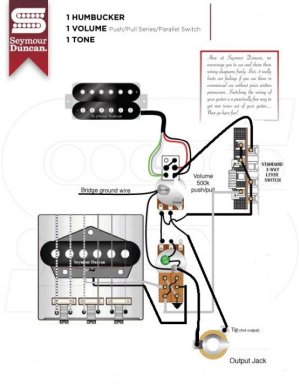
I am doing some work on a friend's Tele. It has a bucker in the neck and a standard tele bridge.

He has asked me for the following:

Position 1 - Neck Parallel
Position 2 - The neck pickup which is parallel still, but the whole thing wired series and out of phase with the bridge
Position 3 - Regular bridge single coil

I'm trying to wrap my noodle around the Position 2, and I could really use a diagram. But doing a search for parallel series out of phase is a bit like trying to throw out you recycling box.
 
Re: Tele Series - Out of Phase Diagram Please -

You would basically need a push/pull for the volume and tone. It would be your choice which push/pull you want to be the phase switch and parallel switch. This should give you the basic idea of what the parallel/series switch and the phase switches would look like.
 

Attachments

  • 1H_1VppSP_1T.jpg
    1H_1VppSP_1T.jpg
    48.8 KB · Views: 0
Last edited:
Re: Tele Series - Out of Phase Diagram Please -

Thanks. Do I have to have push pull switch? He doesn't ever want a series bucker. Only parallel. And he doesn't ever want in phase in the middle. Always out of phase. Sorry if I wasn't clear on that one.
Would using a 5 way switch make this easier?
 
Re: Tele Series - Out of Phase Diagram Please -

Thanks. Do I have to have push pull switch? He doesn't ever want a series bucker. Only parallel. And he doesn't ever want in phase in the middle. Always out of phase. Sorry if I wasn't clear on that one.
Would using a 5 way switch make this easier?
That changes things considerably and makes it easier. Yes the diagram you posted below will work the only thing you will need to do is wire the neck for parallel. Which I think would be black/green together to ground and white/red together to the switch? You would need to play with the bridge single coil and swap leads until you get the two in phase correctly.
 
Re: Tele Series - Out of Phase Diagram Please -

Visualise your selector switch terminals as follows;

IMPORT
1234 5678

OR USA
5678
1234

1 = Bridge PU hot + link to terminal 7
2 = Neck PU Red & Black + link to terminal 3
3 = Link from terminal 3
4 = output to volume pot
5 = Neck PU Green & White
6 = unused
7 = Link from terminal 1
8 = Connection to ground


EDIT - If you do not wish to mess about with magnets and covers, simply swap the red/black and green/white conductor pairs.

The bare ground wire goes to the volume pot chassis, possibly, via the selector switch body.
 
Last edited:
Re: Tele Series - Out of Phase Diagram Please -

You guys are the best! I love this forum. I will fire up the iron and report back.
 
Re: Tele Series - Out of Phase Diagram Please -

You just caught me at the right moment.

I am currently grappling with the '53 Tapped Five-Way circuit in my Fender AVRI '52 Telecaster. Four of the sounds are excellent. IMO, the fifth is "off". I am mulling over what to do about this. Series interconnection was one of the possibilities. Jerry Donahue fake Stratocaster "in between" sound is another. The cocked wah Esquire sound is my third option.

Like your friend, I would prefer to access my sounds from the lever selector switch without resorting to mini toggles, push-pull pots or the Fender S-1 with its flat top metal knob.
 
Back
Top