This is my first post here. Will this wiring diagram work?

speters33w

New member
I am going to completely rewire my guitar. It is an Ibanez RG Prestige knock-off (not Ibanez) and the electronics kind of suck.
I already installed the new pickups I will be using and this improved the sound quality a lot. But it still has crappy pots, etc. The existing configuration has only a .047µF cap and two dime pots.
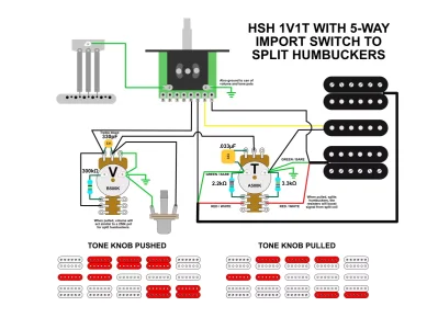
So, I did some nosing around and came up with a wiring scheme. It was important to me to be able to use the bridge and neck humbuckers at the same time, which I will be able to do in position 4.
But I came up with this scheme myself, and while I think it will work just fine I thought I might bounce it around here for critique before I put it all together. Especially if something isn't going to work at all, or if one of you have already tried something I've got here and it stunk.

Thanks for looking!
 

Attachments

  • photo112855.webp
    photo112855.webp
    61.1 KB · Views: 0
Welcome to the forum

It will 'work', but only if the switch is internally configured to have bridge and neck in position 4 already.

I'm not sure why you're doing partial splits with resistors, it doesn't 'boost' signal, but changes the balance of the split coils which changes the sound. I also don't know if I would bother trying to make the volume seem like 250k when the pickups are split. I've had mixed results doing stuff like that.
 
Welcome to the forum

It will 'work', but only if the switch is internally configured to have bridge and neck in position 4 already.

.

Oh I messed up on the wiring to the 5-Way switch. That's why you asked about the configuration. I wouldn't have had both humbuckers like in the scheme.

It's also why I put it up here, to find stupid stuff like that. Here is the corrected drawing:

HSH1T1V_wiring_corrected.webp

As far as the bleed-off resistor to make the pot act like 250k, I figured if it sucks I just won't pull the volume knob. I saw somebody do this with a 470k resistor for volume drop, but it will only be 250k if the volume is all the way up. The taper wouldn't have been right at lower volume levels. With a 330k resistor it will taper better, max resistance would be 200k if the volume is all the way up, so it still might make it quieter.

PRS uses a bleed resister when splitting humbuckers. I saw someone try a bunch of values up to 10K. Clean tones were much better at lower values like 2 or 3k in his examples. PRS uses 1.1K and 2.2K.

Thank you for the response!​
 
When the outside 2 coils are selected, is it cancelling hum?

I really doubt there will be any effect on hum at all by using position 4, the coils are physically too far away for any magnetic field cancelling at all. Those bleed resisters on the tone knob are supposed to help with the hum.

If there is some hum cancelling in position 4 with the tone knob pulled, that would be cool. If there is increased hum then I could use the extra terminals on the volume knob, put the red and white of one of the humbuckers directly across from the 330K resistor, place the black hot on the far terminal, then connect the common to the switch, changing if north or south is the split. This might also increase hum because instead of grounding, the second coil would be floating.

But I really don't think there will be any effect on hum at all because the pickups are physically too far from each other, and there's that single coil between them so there will be no magnetic field to cancel or increase hum.

What I am trying to achieve was the ability to get that beefy grungy sound from an HH, and also have a stratish / teleish single coil sound on demand by splitting the humbuckers without them sounding flat and like crap.

I still have to solder this all together - it is an experiment.

Thank you for your response.
 
You'd have to wire one of the HBs 'backwards' and flip the magnet in the same pickup to get hum-cancelling. With the middle single there, you will get hum sometimes, so that might not be important.
 
You'd have to wire one of the HBs 'backwards' and flip the magnet in the same pickup to get hum-cancelling. With the middle single there, you will get hum sometimes, so that might not be important.

By wiring it "backwards," I would tie the black and shield wire together, leave the red and white as they are and run the green to the switch?

I just checked without removing all the electronics and it looks like the casing of the HBs is tied to ground, I'm guessing through that bare shield wire.
The shielding paint stops at the end of the cavities and doesn't connect to the paint in the wiring cavity, so it isn't through paint.

That actually seems like a good suggestion. I might have to play with the polarity of the middle single to see which way sounds better, I can do that with jumpers before I actually solder to check options.

I am expecting some hum, but that's why God made noise gates.

Thanks, I think I might do it this way.

-Thank you for this suggestion. I like it a lot better than my idea to route the south side through the switch and leave the north floating. My way really sounds like it would induce unwanted noise.

-Stephan.
 
You'd have to wire one of the HBs 'backwards' and flip the magnet in the same pickup to get hum-cancelling. With the middle single there, you will get hum sometimes, so that might not be important.

So with your suggestion the wiring diagram might look like this?

HSH1T1V_wiring-v3.webp
 
Back
Top