Wiring Diagram Q

Neo Fender

New member
I've replaced a few sets of Strat pickups but have never worked with wiring push-pull potentiometers. I have a PRS SE (H/H, 1 Vol, 1 Tone w/ push-pull coil split). I'm replacing the stock 85/15 S pickups with a Jazz neck and a Custom 5 Trembucker on the bridge. While I'm at it, I am adding another push-pull for phase switching. I'm installing new CTS 500K push-pull pots, a new CRL three way blade switch and a new Sprague orange drop .047 microfarad capacitor.

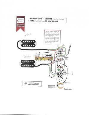
I'm using this diagram as a reference: https://www.seymourduncan.com/images/wiring-diagrams/2H_3B_1VppSPL_1TppPH.jpg

First, I'm sure this is clear to most folks but not so much for me. Trying to confirm how the drawing shows the potentiometer orientation to make sure I'm wiring the push-pulls correctly. Please see the diagram that I've marked up below. I've numbered the switch contacts the way I interpret the drawing.

Second, the poles on my switch are staggered opposite of what the diagram shows. I marked up the drawing to show how the poles on my switch are arranged. On my switch, the top row is offset to the left, whereas on the original SD drawing, the top row if offset to the right. Don't know if this makes a difference. I understand the switch can be installed either way - it just has to be wired correctly.

Clarifications/corrections are appreciated.

Thanks
7oB8RFQh.jpg​​​​​​​
 
First of all, great choice on your pickups. Two of my favorites.

Now, I don't know your level of knowledge about the electrical components in a guitar, so a little instruction first...I'll try to keep it simple, but a good understanding of this will help you immensely in the future.
A push/pull pot is two actually two separate components...the pot, and the switch. The typical p/p switch is what is called a "double pole double throw" switch, or "DPDT" for short. It is actually two independent switches stuck together, one on the left and one on the right, each being a "single pole double throw" switch, or "SPDT". The two terminals in the middle of the DPDT are the "poles" or commons. The terminals on the top and bottom are the "throws". Each pole can make contact to either a top/up throw or a bottom/down throw. In the case of a p/p, the "top" throws are always next to the pot, and are the "up" position of the p/p (no matter how the diagram is oriented). In your diagram, the top throws or "up" position of the p/p in the volume pot is oriented down (next to the pot). When that p/p is in the down position, the poles/commons (C1 and C2) are connected to throws 2 and 4 respectively which are connected to nothing. Therefore the pups are in humbucker mode. When that p/p is pulled up, C1 connects to throw #1 and C2 connects to #3. Those two terminals are directly or indirectly connected to ground so each pup has its red, white, and green wire grounded and the black/hot wire eventually going to the output jack...those pups are "split" to the slug coils.

One important correction...in the tone p/p, terminal #3 should have a wire connecting it to ground (the back of the tone pot).

Some blade switches are made like your diagram. Some are made like yours. They function exactly the same. I know, it's very confusing. The blade switch works similar to the p/p but it is a DPTT (double pole triple throw). Each "pole" or "common" terminal (the terminals where the pickup black wires are connected) can make contact to one of three throws.

So, with that correction I made, your diagram will do what you want. The vol p/p will split the two pups and the tone p/p will change the phase of the bridge pup making the two pups out of phase (OOP) with each other.

Good luck with your wiring. Let us know how it goes and how you like the tones you will be getting. Also let us know if you have any questions as you go.
 
Doc,

Thanks for your response.

I understand everything in your first paragraph. To simplify my concern, I guess my question should be: on my mark up, did I correctly label the terminals on the p/p DPDT terminals?

THANKS!
 
I put a Custom5 into an SE a few years ago. It was perfect for that guitar, sounded great.

If this were my project I'd consider using a .022uF cap instead of .047 which gets dark fairly fast as you turn it down.
For my taste, .022 gives a wider useful range on the tone control, especially for humbuckers.

.047 is more commonly used with bright singlecoils like Strat or Tele pickups.
IMO when it comes to fatter sounding pickups - even P90s, but humbuckers especially - .022 generally works better.

Still, as with any advice on tone, YMMV.

Thanks. I actually realized that yesterday and ordered a .022uF orange drop. I had ".047" burned into my brain from the Strat pickup mods I've done in the past. I have a metalized .022 uF cap available so I may throw that in so I can get this thing back together.
 
Follow up:

I've soldered everything together per the marked up drawing in my OP and grounded terminal 3 per GuitarDoc above . I measured DCR at the output jack Here's what I measured:

Volume and Tone full CW (dimed)

Phase in or out did not affect DCR (expected)

Bridge: 14.82K: expected
Neck: 7.14K: expected

Bridge (split) 14.82K: expected approximately half this value
Neck (split) 3.6K : expected

DCR with volume fully CCW: 0.

Seems like the bridge pickup is not splitting. Would appreciate feedback on what to look for.
 
The bridge isn't splitting because nowhere on your wiring do the bridge red and white get grounded.

I would have started with one push-pull dedicated to coil splits only, then figured out a way to phase flip the bridge using the second push-pull, coil split or not.

With only two knobs to work with your options are limited, but a five-way switch Superswitch or a Schaller Megaswitch might help. The other option might include a separate DPDT mini switch.

I wired my HH Strat with a 5-way Superswitch to give full humbuckers in P1 P3 and P5, and auto coil splits in P2 and P4. I could just have easily wired it for auto coil splitting in P3 if I'd wanted to.

The way you do auto coil splits in P2 and P4, but not P3, is to wire the reds and whites to P2 and P4 on one switch bank and to ground the common lug on the same bank. That way in P2 and P4 only, the red/white pair gets grounded.

If you want auto coil splits in P2, P3 and P4 I think you need to use two individual switch banks, one for the bridge and one for the neck. Otherwise you create a permanent short between the reds and whites. Wire the bridge red/ white up to one switch bank P2 and put a jumper across to the P3 lug, ground the common. Repeat with the neck on a separate switch bank using P3 and P4.

Using a regular 5- way you can arrange the pickups to auto coil split in P2 and P4 only by connecting the reds and whites to the neck and bridge lugs, and directly ground the middle lug. Don't ground the common. In P1 the bridge red and white don't go anywhere. In P2 the red and white connect to the middle lug and thus to ground. In P3 neither set of red or whites go anywhere. P4 and P5 are like P2 and P1, in that order, but for the neck,
 
So...as drawn, the Seymour Duncan diagram will not work? If so, are you saying there is no way to do split and phase two HBs with one volume, one tone with attached DPDTs? I can go the Megaswitch route but I'd rather not drill into the guitar for additional switches.
 
Last edited:
I've been looking at it and I THINK the problem is that 3 on the tone pot-push pull should be grounded.

With the volume push-pull set to push (full humbucker) the red and white pair go nowhere (except to each other) and so you get full humbucker. So the connections on the volume pot itself aren't the problem.

Now let's look at the tone pot push-pull.

In push, normal phase, no coil split, the black goes to C2, then to 4, jumps across to 1 (which isn't connected to C1) and then to the selector switch. Good

In push, normal phase, no coil split, the green (ground) connects to C1, connects to 2, jumps to 3, which isn't connected to anything. so the bridge humbucker ground doesn't appeared to be connected to ground there. The green also connects, via C1 to 3 on the volume pot push-pull. If the volume pot is in push, the connection goes nowhere. So you still don't have a ground for the bridge humbucker. In pull it shorts with the red and white connected to C2 on the volume push-pull. This neutralises the red/green pair and thus the humbucker south coil, but the white still isn't grounded on the tone push-pull when the tone push-pull is pushed.

Now let's look at the tone pot / bridge green again with 3 on the tone push-pull grounded.

In push, normal phase, no coil split, the green (ground) connects to C1, connects to 2, jumps to 3, which is now grounded. So in full humbucker you have a ground via the green.

The green also connects, via C1 to 3 on the volume pot push-pull. If the volume pot is in push, the connection goes nowhere. If the volume is in pull it connects the green to the red neutralizing the south coil, and the north coil white is now controlled by the tone pot push-pull.

If the tone pot push-pull is in push (normal phase) the coil split white is connected via 3 on the volume pot push-pull to C1 on the tone push-pull. In push (normal phase) C1 is connected to 2, jumps across to 3, then to ground. So the white now has a ground.

If the tone push-pull is in pull (phase flip) the white is connected to C1 then to 1 then to the selector switch, so the white is now the hot. The black is connected to C2 and in pull connects to 3, and now to ground.
 
Well, if that doesn't solve it and with two of us reviewing the SD wiring diagram independently, I'm stumped.

Look at your soldering on the push-pulls. Use a multimeter to check for bad solder joints and also check to make sure you haven't inadvertently created any little solder "bridges" between contacts.

Make sure you haven't inadverinadver"cooked" one or both of the push pulls too.
 
Last edited:
PS if it's only the bridge push pull coil split that's not working, and if you've added the extra ground, start with the red/white pair soldering on the volume push pull, then the wire to the tone push pull, then that the push pull is working properly, and so on.
 
Found it. I did not have the #3 terminal on the volume pot connected to C1 on the tone pot. Everything is now measuring as I think it should. Will fire it up later.

Thank you very much for your time and knowledge. Both are sincerely appreciated.
 
Found it. I did not have the #3 terminal on the volume pot connected to C1 on the tone pot. Everything is now measuring as I think it should. Will fire it up later.

Thank you very much for your time and knowledge. Both are sincerely appreciated.

Yeah, that's an important connection to make...without it, the bridge pup will not split. All should be fine now.
 
Back
Top