
 Tweet
Tweet
Hi, I'm new around here! Thought I'm pretty sure I've read some threads while looking for other stuff. Looks like a good community, with a lot of knowledgeable and helpful people!
And I need help with a pup configuration (I did do some searching but couldn't find what I was looking for):
I use an RG321MH with a JB in the Bridge and a Jazz in the Neck and I like the way it's wired, except for the 4th position (neck in parallel). What I want is this:
1-Bridge (series)
2-Inner coils
3-Bridge and Neck (I think the wiring I have puts them in series. Standard RG321 wiring.)
4-Bridge (series) and Neck outer coil (To get the brightness of the bridge pup and roundness of a single coil(esque) neck pick up. I hope.)
5-Neck (series)
I've read articles but I still don't get it. How to do this wiring with a 5-way super-switch (Fender), I mean. And I build my own effects clones... I should be able to grasp that, but nope...
I don't know whether position 4 should put the bridge pup and outer in series or in parallel...?
So, I'm looking for advice on the later and hopefully a diagram for the wiring I want. I'm probably gonna try other configs as time goes by, but I want to start with this one.
Thanks in advance for any help you guys and gals can provide!


 It has some chunk and jangle. If that makes any more sense... And the Brige coil-tap on its own is *really* nice. Not a signle-coil, but I like it, especially with my auto-wah (MXR Envelope Filter). You can get a very nice 'quack' out of it.
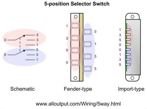

Comment