banner

Announcement

Collapse
No announcement yet.

5 Way Switch Wish

Collapse
X
 
  • Filter
  • Time
  • Show
Clear All
new posts

  • 5 Way Switch Wish

    Hi,

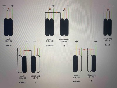
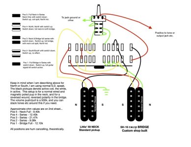
    New here, though not too new to guitar wiring. I have created a little problem for myself, that I cannot seem to solve. Attached are the results of a bread board breakout with the best sounding wiring configurations for these two pickups, at least to my ears. I have tried several ways to wire this using a 5 way, 4 pole super switch with "outs" at the opposing sides, and no can find. I also added one volume with a push/pull switch attached, but still cannot find a solution to the get this exact wiring scheme. It would be great if I could find a way with only the super switch, so I thought I would try this forum. I have one F spaced, rwrp SH-16 I custom ordered for this application, as well as a standard Little' 59. Anyone have any thoughts on how to achieve this scheme? I am not opposed to having to add more positions say with other blade switch or adding other components.
    Last edited by Rickygene; 06-14-2021, 08:31 AM.

  • #2
    I am having a similar issue getting this exact wiring with a rw/rp neck pickup and haven't come up with the solution. I am getting both the neck side coils and the bridge side coils but not inner and outer coils. I even made a thread about it!
    At least my configuration is hum-cancelling. But I'd love to see the solution to this.
    Administrator of the SDUGF

    Comment


    • #3
      I'm studying both threads. I need more libations.

      I haven't given up yet, but I have too take breaks for occasional customers.

      Comment


      • #4
        Originally posted by Rickygene View Post
        Hi,

        New here, though not too new to guitar wiring. I have created a little problem for myself, that I cannot seem to solve. Attached are the results of a bread board breakout with the best sounding wiring configurations for these two pickups, at least to my ears. I have tried several ways to wire this using a 5 way, 4 pole super switch with "outs" at the opposing sides, and no can find. I also added one volume with a push/pull switch attached, but still cannot find a solution to the get this exact wiring scheme. It would be great if I could find a way with only the super switch, so I thought I would try this forum. I have one F spaced, rwrp SH-16 I custom ordered for this application, as well as a standard Little' 59. Anyone have any thoughts on how to achieve this scheme? I am not opposed to having to add more positions say with other blade switch or adding other components.
        Before I get into how to have a switch yield the positions you want, i have some comments/questions about the wires that you are using as Hot and Cold on each pickup.

        Your diagram labels the SH-16 as RWRP, which from what Mincer and I have recently encountered from two other SD RWRP pickups, is that RWRP designs causes the polarities of all 4 wires to reverse, so that Green is now Hot and Black is now Cold. But your diagram labels Green as - , as if the polarity was not reversed. *sometimes* SD makes a RWRP pup where the wire colors were swapped around too, but we've only seen those so far in pickups that SD made for a guitar manufacturer as their OEM pickups.... i.e., not pickups available for sale directly to the consumer. Have you used a multimeter to confirm that Green wire has a - polarity in your RWRP SH-16? Here's a link to a Youtube tutorial video on how to use a multimeter to check that. Particularly from minutes 4 to 10. This tutorial has alot of other super useful how-to's using the metet that is worth your while to check out. https://youtu.be/7UfxQBhqen8


        So I assume how you're still using SH-16's Black wire as Hot (+) when I suspect it is now Cold (-) due to its RWRP design, is why you've wired the Lil 59 in reverse, cuz you're having to compensate for how you have the SH-16 wired? In general practice, its best to wire the pickup in reverse, that actually has the reversed polarity, instead of other pickupe that don't. Yes, how you've done it here should work fine, but in terms of being able to decipher it years later should you need to do maintenance in that guitar like replace a pot or change out one of the pickups, and you've long since forgotten why the wires are in reverse, that's what i'm talking about.
        Last edited by Jack_TriPpEr; 06-14-2021, 11:48 AM.
        Sanford: "The hardest part about tone chasing is losing the expectations associated with the hardware."

        Comment


        • #5
          Man, that video made me recall that I learned that years ago, just forgot about it! Please disregard my diagram, until I have a chance to update it with the verified hot and cold sides. Thank you!

          Comment


          • #6
            Originally posted by Rickygene
            Clearer jpg, I think
            Please confirm for me if my following interpretation of what you want is correct (+ = In Series connection, / = In Parallel connection):

            1. Bridge full HB
            2. Bridge Outer Coil + Neck Inner Coil
            3. Neck full HB + Bridge Full HB
            4. Neck Outer Coil + Bridge Inner Coil
            5. Neck full HB

            ?
            Sanford: "The hardest part about tone chasing is losing the expectations associated with the hardware."

            Comment


            • #7
              Originally posted by Rickygene
              Clearer jpg, I think
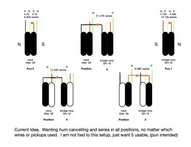
              Somethings wrong with your DC resistance measurements. For each pickup, the sum of the two individual coils measurements should equal the In Series measurement for that pickup.
              Sanford: "The hardest part about tone chasing is losing the expectations associated with the hardware."

              Comment


              • #8
                I expect that the meter checks would have told you that Red and Green wires are for the Screw coil of the Sh-16? And black and white wires are the Slug coil?

                And for the Lil 59, that - with the pickup oriented so that the SD logo reads the correct way (i.e. not upside down), that the upper coil is black and white wires? And the lower coil is the red & green wires?

                If the meter confirmed all the above as accurate, then those are the wires that you test together when performing your DC Resistance measurements.

                Sanford: "The hardest part about tone chasing is losing the expectations associated with the hardware."

                Comment


                • #9
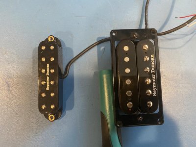
                  Ugh, your right! When I was making the file, I lost track of what ohm measurement went where. They are now correct, as I remeasured everything to be sure and documented what is. Additionally, the photo with the pups is the same orientation as the diagram (diagram does not illustrate this, though if needed, I can do so. Please note that I forgot to tie the white (yellow for illustration purposes), and red together for Position Number 3. I was not sure how to reflect the remaining wires in 2 & 4, so I left that for interpretation. And also yes, the black pickups in the drawing are to be the active at the time live ones in respect to the position of the switch. Thank you, Rick.
                  Attached Files
                  Last edited by Rickygene; 06-14-2021, 03:07 PM.

                  Comment


                  • #10
                    Originally posted by Jack_TriPpEr View Post
                    And for the Lil 59, that - with the pickup oriented so that the SD logo reads the correct way (i.e. not upside down), that the upper coil is black and white wires? And the lower coil is the red & green wires?
                    For what it's worth, I just checked a Cool Rails neck, Hot Rails bridge, CS PGn, CS PGb, and a Lil Screamin' Demon bridge, and all of them are as you say . . . neck side coils are B/W regardless of whether it's a neck or bridge pup.

                    Comment


                    • #11
                      Originally posted by ArtieToo View Post

                      For what it's worth, I just checked a Cool Rails neck, Hot Rails bridge, CS PGn, CS PGb, and a Lil Screamin' Demon bridge, and all of them are as you say . . . neck side coils are B/W regardless of whether it's a neck or bridge pup.
                      Thanks. Seemed odd at first for a neck pup to be oriented that way, but after I gave it more thought, i figured that was done because a lil bucker is most often being installed in a guitat with a middle pickup, so that magnet orientation helps get hum-canceling coilsplit pairs since singlecoils are traditionally south up oriented
                      Sanford: "The hardest part about tone chasing is losing the expectations associated with the hardware."

                      Comment


                      • #12
                        And I'm glad you brought that up. I wouldn't have thought that, and wouldn't have measured them before wiring them up.

                        I really gotta start doing that meter / compass test on all pup installs.

                        Comment


                        • #13
                          Originally posted by ArtieToo View Post
                          And I'm glad you brought that up. I wouldn't have thought that, and wouldn't have measured them before wiring them up.

                          I really gotta start doing that meter / compass test on all pup installs.
                          Thanks Artie. I always appreciate your insights and assistance. .
                          Sanford: "The hardest part about tone chasing is losing the expectations associated with the hardware."

                          Comment


                          • #14
                            And back atcha. The Gaussmeter from Kewlsoft is a pretty nice app. They have a good compass too. On Google Play.

                            Comment


                            • #15
                              Well, once master Jack Tripper https://forum.seymourduncan.com/memb...6-jack_tripper , pointed me in the right direction, I have achieved what I wanted. While I know this may be highly open to judgement, I worked it out appropriately and each position sounds great, to my ears. The switch is a 'super switch' with outs on each end. If you wire this the way the switch is depicted, then when the toggle is in the far right, that will be the Bridge, or Position number 1. I believe all positions are hum cancelling. If you do not count the fact that the up position on the dpdt switch is a kill switch in position 1, and does nothing in the up position on switch 2, then you will end up with 8 usable signal positions, each one a little different. Let me know your thoughts or if you think I have flipped my lid .... I am calling this wiring scheme, "Rick's Wacky Wiring". (Note: All yellow wires in both diagrams are depicting white Seymour Duncan, simply for illustration purposes).
                              Last edited by Rickygene; 06-14-2021, 08:48 PM.

                              Comment

                              Working...
                              X