banner

Announcement

Collapse
No announcement yet.

Triple Shot switch modification

Collapse
X
 
  • Filter
  • Time
  • Show
Clear All
new posts

  • Triple Shot switch modification

    I am in the midst of a jazzmaster type build and had bought the p-rails+triple shot to use on it. however with the pickguard i dont need the rings. also jazzmasters have the 2 way switch for the r/l selection.

    The switch that's used in Jazzmasters and Jaguars. This is the brand used in original Fender production beginning in 1958, and in USA reissues.


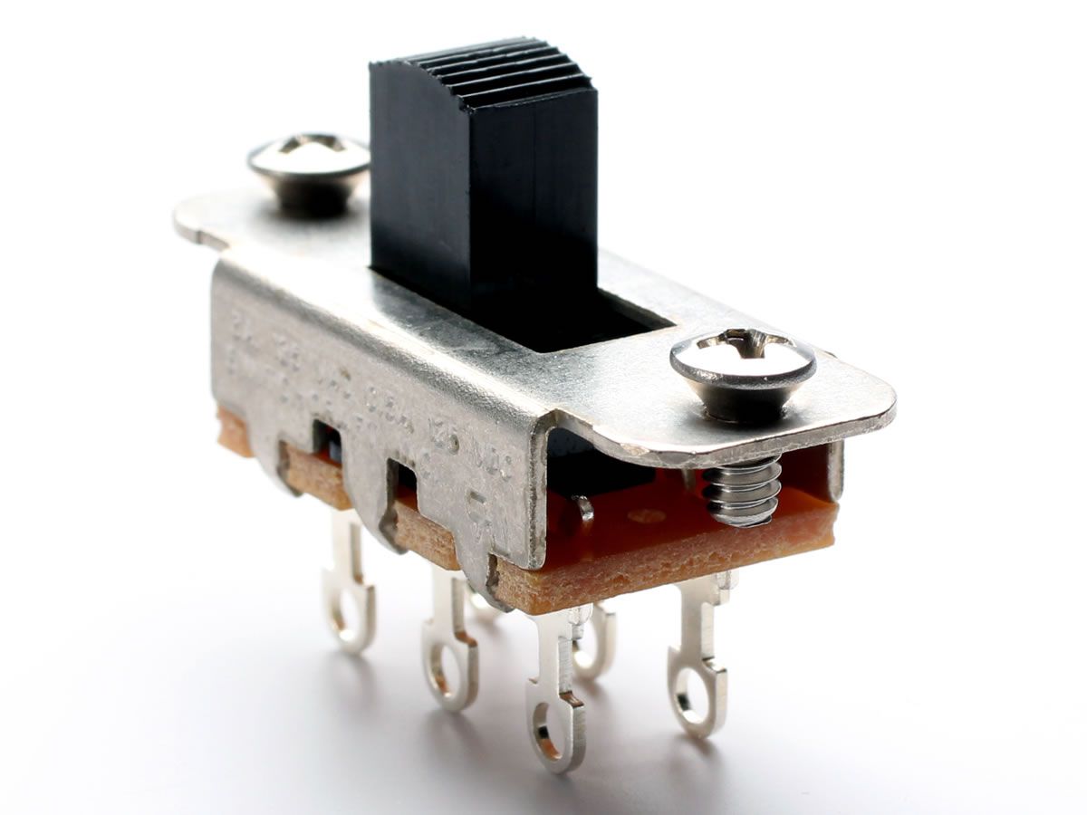
    i'm custom cutting my pickguard so was thinking of getting 4 of these switches [they are also beefier than the 3shots ones] and mount them in a similar location above the pickups. anyone know what the wiring would be to two of these switches from the ribbon cable. there are 4 leads, 3 grey and 1 red coming off the pcb. something a bit like this. rest of wiring is 1 volume, 2 tone, 3way switch. or am i going to have to desolder the switches on the switch pdb and hardwire to those points and not the ribbon cable?

    Click image for larger version

Name:	jizzmaster mucha.jpg
Views:	165
Size:	93.0 KB
ID:	6230314
    Attached Files

  • #2
    I wouldn't advise attempting to solder with ribbon cable wires. Those are very delicate and made for surface mount technology that uses a different kind of solder that is reflowed in a lower temperature oven in order to solidify the connection.

    I think you need to, possibly with a lower temperature solder iron, remove the P-Rail pickup wires from the PC board and use those to connect to your pickguard switches.

    Pickguard switch wiring would be:

    Switch 1
    A - connect to 2A
    B - pickup red wire
    C - pickup black wire (to switch, hot)

    Switch 2
    C - pickup green wire (to ground)
    B - pickup white wire
    A - connect to 1A

    Consider switch 1A is toward the neck, and switch 2A is toward the bridge. You only need one side of the switch (the other three lugs can be left empty)

    Comment


    • #3
      love the concept! and the guard looks sweet

      Comment


      • #4
        so wouldnt even need the triple shot PCB? still trying to figure out your wiring on that, but i have also been on the road for 12 hours just getting home... i have been playing a bit around with the placement for these larger switches and not sure if i can fit them all realistically. i may have to use the triple shot switches after all and just take the ring off and cut slots in the pickguard for them and mount them sans ring. now that im back home i may try a cut to test with the triple shot pcb thats on the ring.

        i was just thinking if i could keep it a little closer to a jazzmaster with their switches. i may have to do something like this?

        Click image for larger version

Name:	jizzmaster mucha-altswitch.jpg
Views:	138
Size:	29.9 KB
ID:	6230386

        Comment


        • #5
          Originally posted by jeremy View Post
          love the concept! and the guard looks sweet
          thanks. not sure i am allowed to share my whole concept on this forum [some may get offended]. but the body is mahogany, walnut, cherry, ipe, maple of various widths, kind of like an old wooden surfboard. bigsby, p-rails... etc. maple neck.

          Comment


          • #6
            Originally posted by beaubrummels View Post
            Pickguard switch wiring would be:

            Switch 1
            A - connect to 2A
            B - pickup red wire
            C - pickup black wire (to switch, hot)

            Switch 2
            C - pickup green wire (to ground)
            B - pickup white wire
            A - connect to 1A

            Consider switch 1A is toward the neck, and switch 2A is toward the bridge.
            so this is basically the triple shot wiring on the PCB? grabbed mine now that im home to look at pcb. this will give me series, parallel, each coil? [up/up, down/up, up/down, down/down--- had to relocate the switches to fit so have to make them vertical, see above]

            Comment


            • #7
              like this?

              Click image for larger version

Name:	3shot wiring.jpg
Views:	140
Size:	26.5 KB
ID:	6230395

              Comment


              • #8
                not sure if thats how 3shot is wired. looking at pcb its

                black goes to sw1 port 2 then bridged to 4
                green goes to sw2 port 6
                sw1 port 6 is bridged to s2 port 4
                sw2 port 2 and 5 are bridged
                white goes to sw2 port 2
                red i think goes to sw1 port 1

                then there is a "bridge" between sw1 port 6 and sw2 port 3 marked as C1 to pads thats not connected.... not sure purpose of this on the pcb. obviously isnt connected together.
                Last edited by prokreat; 04-22-2023, 10:39 AM.

                Comment


                • #9

                  something like this as far as i can tell from looking at PCB

                  Click image for larger version

Name:	3SHOT PCB.jpg
Views:	134
Size:	32.5 KB
ID:	6230438

                  Comment


                  • #10
                    of course after a little googling found this

                    Click image for larger version

Name:	ts-toggle-jpg.86982.jpg
Views:	122
Size:	67.6 KB
ID:	6230440

                    Comment


                    • #11
                      Originally posted by prokreat View Post
                      of course after a little googling found this

                      Click image for larger version

Name:	ts-toggle-jpg.86982.jpg
Views:	122
Size:	67.6 KB
ID:	6230440
                      The switches are wrong in that drawing. You'll never get full humbucking with that wiring because red is tied to hot and white is tied to ground.

                      Comment


                      • #12
                        Originally posted by prokreat View Post
                        like this?

                        Click image for larger version

Name:	3shot wiring.jpg
Views:	140
Size:	26.5 KB
ID:	6230395
                        That drawing won't work. You only use one side of the switches. You need all the connections on the same side of each switch. Switches are not bridged automatically from one side to the other. You've got DPDT (Dual Pole, Dual Throw) switches, which is the same as having two independent SPDT (Single Pole, Dual Throw) switches on one switch knob.

                        Comment


                        • #13
                          Originally posted by prokreat View Post
                          something like this as far as i can tell from looking at PCB

                          Click image for larger version

Name:	3SHOT PCB.jpg
Views:	134
Size:	32.5 KB
ID:	6230438
                          Don't copy the PCB. Your switches are different, and you can't see all the layers on the PCB to be sure what's going on there.

                          Triple shot wiring with SPDT or DPDT is simple. Don't over complicate it.

                          Hopefully this makes it even simpler...

                          Switch A
                          1 - jumper to B1
                          2 - White wire
                          3 - ground (any nearby ground connection, doesn't matter)

                          Switch B
                          1 - jumper to A1
                          2 - Red wire
                          3 - hot to the switch for this pickup (so it follows pickup selection)

                          Comment


                          • #14
                            Originally posted by beaubrummels View Post

                            The switches are wrong in that drawing. You'll never get full humbucking with that wiring because red is tied to hot and white is tied to ground.
                            Actually, it will. The drawing has a "top" and "bottom" half. The top half is "normal", while the bottom half is for flipped wiring.

                            Click image for larger version

Name:	toggles.jpg
Views:	175
Size:	49.1 KB
ID:	6230468

                            Comment


                            • #15
                              Originally posted by beaubrummels View Post

                              That drawing won't work. You only use one side of the switches. You need all the connections on the same side of each switch. Switches are not bridged automatically from one side to the other. You've got DPDT (Dual Pole, Dual Throw) switches, which is the same as having two independent SPDT (Single Pole, Dual Throw) switches on one switch knob.
                              so if i take that diagram, its correct if i make all the connections on a single side?

                              Comment

                              Working...
                              X