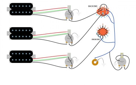
3 Humbucker diagram

Galva

New member
I am planning on doing a 3 Humbucker build and was searching for a diagram to use, when I found the following post, last updated in 2010:

In answer #8 it says that a guest is using
[...] a 6 position rotary (4P6T), 4 p/p pots configured as 3 vol 1 tone. Each pickup's volume pot can be pulled to achieve split coil, and the middle pickup is split to the south coil so that you can achieve hum-canceling in postions 2 and 4. When split in position 6 it is the north coil of the neck and the south coil of the bridge to provide hum-canceling.

These are the switching options
1-Neck
2-Middle/Neck parallel
3-Middle
4-Middle/Bridge parallel
5-Bridge
6-Bridge/Neck parallel
each pickup can be split individually


on the tone pot i used a p/p pot to switch between 2 different caps on the tone control, but this is not necessary, I just wanted the option.

Does anyone know where to find this diagram? The link to the image is unfortunately not working anymore.

Thanks in advance
 
Re: 3 Humbucker diagram

I have managed to find some diagrams by him, including this one:

3hum5wayswitchCustomMkIII.png

Can anyone confirm that this diagram does what he described in his answer?

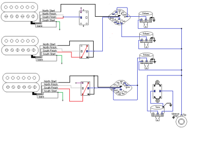
I have now tried to replicate the diagram as follows:
diagram hhh.jpg
(these are the neck, middle and bridge pickups respectively, with their volume pots and one master tone, with .022uF and .047uF)

Would this result in the desired positions?

These are the switching options
1-Neck
2-Middle/Neck parallel
3-Middle
4-Middle/Bridge parallel
5-Bridge
6-Bridge/Neck parallel
each pickup can be split individually

Could anyone explain to me what nalo1022 was using the fourth part of the rotary switch for?

Thanks very much
 
Last edited:
Re: 3 Humbucker diagram

I am planning on doing a 3 Humbucker build and was searching for a diagram to use, when I found the following post, last updated in 2010:

In answer #8 it says that a guest is using

Does anyone know where to find this diagram? The link to the image is unfortunately not working anymore.

Thanks in advance

are these the 6 pickup selections you want? Plus you want splits on all hum buckers or just a couple? I am not really understanding the diagram and why it seems complicated. Will your hum buckers have pickup rings?
 
Re: 3 Humbucker diagram

The idea was to have 3 Humbuckers that can be split individually using the push/pull on their respective volume pot. Then the three outputs go into the 6 way rotary seitch, where I have hopefully wired these outputs to the six combinations mentioned above. Afterwards one additional push/pull selects between two different capacitors.
Basically I am not sure if the order of pickup/split/switch is correct, and whether I have wired the switch correctly, as I have never used one before.
Also I'd rather not use triple shots if possible...
 
Back
Top