turbothighs
New member
Hello!
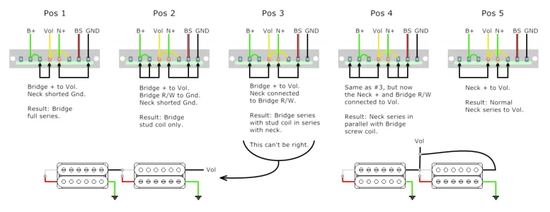
I am working on a custom build for myself and I’m trying to use this Strandberg wiring diagram:

I got everything wired up, and positions 1-3 sound okay with my screwdriver tap test, but positions 4 and 5 have no output. I identified that there is a ground loop happening in those two positions, and by removing one wire at a time, I traced it to the ground wire that runs off of lug 8. Removing that wire removes the ground loop (but also changes the switch behavior, so it’s not really a fix). Here’s my current wiring situation (lug 8 is gator clipped for testing purposes):

My three main questions are:
Thanks in advance for any help!
I am working on a custom build for myself and I’m trying to use this Strandberg wiring diagram:
I got everything wired up, and positions 1-3 sound okay with my screwdriver tap test, but positions 4 and 5 have no output. I identified that there is a ground loop happening in those two positions, and by removing one wire at a time, I traced it to the ground wire that runs off of lug 8. Removing that wire removes the ground loop (but also changes the switch behavior, so it’s not really a fix). Here’s my current wiring situation (lug 8 is gator clipped for testing purposes):
My three main questions are:
- What is the purpose of the ground wire running from lug 8 in the diagram? My understanding of 5 way switches would mean that it’s just introducing a ground loop in positions 4 and 5 - what am I missing there?
- If it’s not expected that that wire introduces a ground loop (which I’m assuming), what should I check around that wire to try to troubleshoot? I’ve already completely replaced that wire with a fresh one and that didn’t fix anything, so I don’t think it’s an issue with the wire/joints, but I could be wrong of course.
- The switch I’m using (Kaish 5-way) came with a bridge between lugs 4 and 5 from the factory. I saw that those lugs were colored differently in the diagram, so I assumed that represented the factory bridge and left it in. I did try clipping it at one point, but all that did was kill my 3rd position, so I soldered it back. However, I did cross poss this to Reddit and someone there suggested that may be what’s breaking my circuit. Thoughts?
Thanks in advance for any help!