Hi,
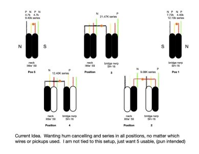
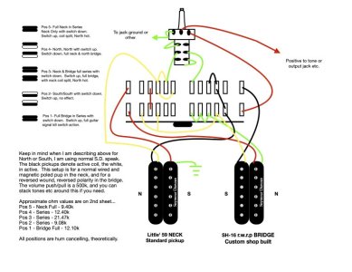
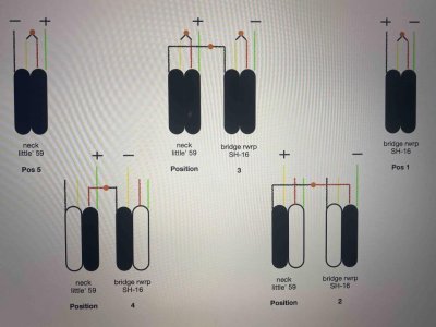
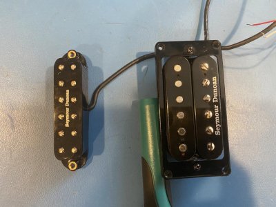
New here, though not too new to guitar wiring. I have created a little problem for myself, that I cannot seem to solve. Attached are the results of a bread board breakout with the best sounding wiring configurations for these two pickups, at least to my ears. I have tried several ways to wire this using a 5 way, 4 pole super switch with "outs" at the opposing sides, and no can find. I also added one volume with a push/pull switch attached, but still cannot find a solution to the get this exact wiring scheme. It would be great if I could find a way with only the super switch, so I thought I would try this forum. I have one F spaced, rwrp SH-16 I custom ordered for this application, as well as a standard Little' 59. Anyone have any thoughts on how to achieve this scheme? I am not opposed to having to add more positions say with other blade switch or adding other components.
New here, though not too new to guitar wiring. I have created a little problem for myself, that I cannot seem to solve. Attached are the results of a bread board breakout with the best sounding wiring configurations for these two pickups, at least to my ears. I have tried several ways to wire this using a 5 way, 4 pole super switch with "outs" at the opposing sides, and no can find. I also added one volume with a push/pull switch attached, but still cannot find a solution to the get this exact wiring scheme. It would be great if I could find a way with only the super switch, so I thought I would try this forum. I have one F spaced, rwrp SH-16 I custom ordered for this application, as well as a standard Little' 59. Anyone have any thoughts on how to achieve this scheme? I am not opposed to having to add more positions say with other blade switch or adding other components.
Attachments
Last edited:


") .
.