Gstring
Active member
.
Have been experimenting for some time with the re wiring one of my favourite 2 vol 2 tone mahogany/maple arch tops. It has 4 CTS push pulls which now give Artie's coil swap , partial coil cut for each pup and a combined Series/OOPs. Have now found a wiring I like but would be interested to learn what is happening theory wise.re the partial coil cut.
My trial and error experiments have been primarily with the partial coil cuts to get a slightly better (different?)sound than either standard parallel or a straight coil cut. Experiments comparing sounds after adjustments with a single guitar are always a bit hit or miss relying on ear memory but I think I am getting to where I want to be.
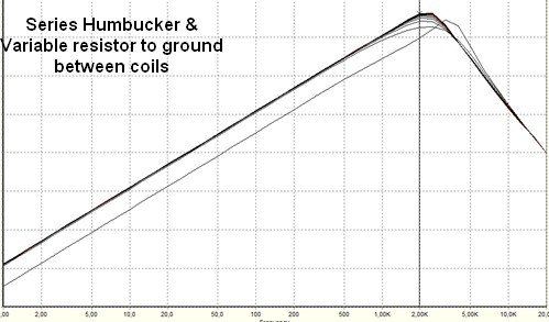
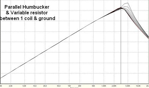
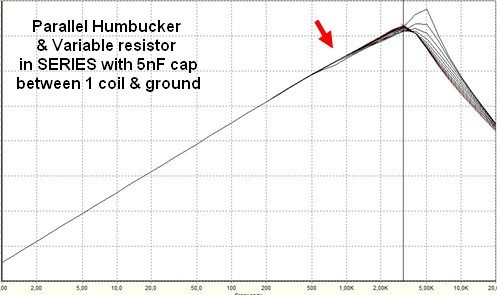
I have found that I prefer the sound of partial coil cuts so that the by bypass filter works only on one coil when the pup is wired in parallel. See extract of my schematic. For simplicity PPs are shown as standard as opposed to convoluted CTS wiring. This wiring I think also gives improved sounds when both the coil swap and partial cut are engaged. Also I think I can hear a slightly sweeter sound iwith a small 0.05 cap added in series to the resistor.
I am at the moment using 500k pots( cheap imports I had lying around) as resistors to find a value I like . Current favourite values seem to be around 375 ohm for the bridge and 210 for the neck. Single resistors of similar values will eventually be fitted to neaten things up under the hood.
My electrical theory is very limited and I would be interested to learn from some one more knowledgeable what is the difference in terms of current flow of wiring a partial coil cut as normal (as in fig 1) or of how I have wired it (fig 2) . Also what is it that happens to the “frequency filter” when you wire a small cap in series with a resistor as I have done. I was intrigued out of curiosity to try resistor and cap in parallel as per the de mud mod but never got around to it. If anybody can tell me the likely result in a partial ciol cut situation it would be appreciated.

Have been experimenting for some time with the re wiring one of my favourite 2 vol 2 tone mahogany/maple arch tops. It has 4 CTS push pulls which now give Artie's coil swap , partial coil cut for each pup and a combined Series/OOPs. Have now found a wiring I like but would be interested to learn what is happening theory wise.re the partial coil cut.
My trial and error experiments have been primarily with the partial coil cuts to get a slightly better (different?)sound than either standard parallel or a straight coil cut. Experiments comparing sounds after adjustments with a single guitar are always a bit hit or miss relying on ear memory but I think I am getting to where I want to be.
I have found that I prefer the sound of partial coil cuts so that the by bypass filter works only on one coil when the pup is wired in parallel. See extract of my schematic. For simplicity PPs are shown as standard as opposed to convoluted CTS wiring. This wiring I think also gives improved sounds when both the coil swap and partial cut are engaged. Also I think I can hear a slightly sweeter sound iwith a small 0.05 cap added in series to the resistor.
I am at the moment using 500k pots( cheap imports I had lying around) as resistors to find a value I like . Current favourite values seem to be around 375 ohm for the bridge and 210 for the neck. Single resistors of similar values will eventually be fitted to neaten things up under the hood.
My electrical theory is very limited and I would be interested to learn from some one more knowledgeable what is the difference in terms of current flow of wiring a partial coil cut as normal (as in fig 1) or of how I have wired it (fig 2) . Also what is it that happens to the “frequency filter” when you wire a small cap in series with a resistor as I have done. I was intrigued out of curiosity to try resistor and cap in parallel as per the de mud mod but never got around to it. If anybody can tell me the likely result in a partial ciol cut situation it would be appreciated.

")