Hi all,
I'm currently attempting to replace the stock pickups in my Fender Telecaster Road Worn guitar with SD's vintage stack (STK-T1n and STK-T3b), using a four way switch.
I wired everything up according to the appropriate SD diagram. The neck pickup worked fine, but the bridge did not.
I thought I had got the switch wiring wrong, so re-did it. Same result.
After watching dozens of youtube videos, I decided to test the resistance of both my new SD pickups as well as my old pickups (I know, I should have done this earlier!!!!). Sure enough, the neck pickup had a resistance value, so too do my old pickups. But my new SD bridge pickup does not.
I want to make sure I am testing correctly. Is it correct to test from the green across to black wires in the STK-T3b? I get a zero reading. Am I doing something wrong?
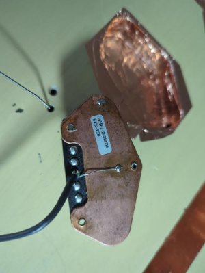
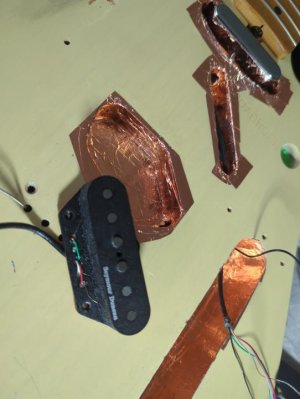
I've also included a picture of the bridge pickup. Is there anything visible that looks wrong?
Appreciate any help.
Cheers
AJ
I'm currently attempting to replace the stock pickups in my Fender Telecaster Road Worn guitar with SD's vintage stack (STK-T1n and STK-T3b), using a four way switch.
I wired everything up according to the appropriate SD diagram. The neck pickup worked fine, but the bridge did not.
I thought I had got the switch wiring wrong, so re-did it. Same result.
After watching dozens of youtube videos, I decided to test the resistance of both my new SD pickups as well as my old pickups (I know, I should have done this earlier!!!!). Sure enough, the neck pickup had a resistance value, so too do my old pickups. But my new SD bridge pickup does not.
I want to make sure I am testing correctly. Is it correct to test from the green across to black wires in the STK-T3b? I get a zero reading. Am I doing something wrong?
I've also included a picture of the bridge pickup. Is there anything visible that looks wrong?
Appreciate any help.
Cheers
AJ
")