You are using an out of date browser. It may not display this or other websites correctly.
You should upgrade or use an alternative browser.
You should upgrade or use an alternative browser.
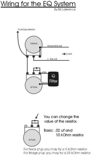
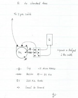
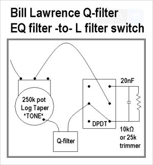
Bill Lawrence Q-filter schematics anyone?
- Thread starter uOpt
- Start date
PFDarkside
of the Forum
Re: Bill Lawrence Q-filter schematics anyone?
What is a Q filter?
What is a Q filter?
uOpt
Something Cool
Re: Bill Lawrence Q-filter schematics anyone?
You use it to put a LCR network into the guitar.
A LCR network is a passive tone circuit, one of the few passive circuits that you can use with regular high-impedance pickups and no preamp.
A LCR network removes impedance from the circuit. That is an important "trick" because your passive pickup has capacitance, impedance and resistance and forms a 2nd class low pass filter (with resonance peak). As you put on more or less wire all these three properties change in combination, you cannot control one without the others. The LCR network will do that for you.
The sound gets "sweeter" in lack of a better word.
A prominent user is Blackmore. He uses a black box that his ex-roadie makes and now sells on the internet for silly money. The exact values of the thing Blackmore uses aren't known but nothing that some experimentation can't fix.
Why is this message so long. Oh it's summer time.
What is a Q filter?
You use it to put a LCR network into the guitar.
A LCR network is a passive tone circuit, one of the few passive circuits that you can use with regular high-impedance pickups and no preamp.
A LCR network removes impedance from the circuit. That is an important "trick" because your passive pickup has capacitance, impedance and resistance and forms a 2nd class low pass filter (with resonance peak). As you put on more or less wire all these three properties change in combination, you cannot control one without the others. The LCR network will do that for you.
The sound gets "sweeter" in lack of a better word.
A prominent user is Blackmore. He uses a black box that his ex-roadie makes and now sells on the internet for silly money. The exact values of the thing Blackmore uses aren't known but nothing that some experimentation can't fix.
Why is this message so long. Oh it's summer time.
PFDarkside
of the Forum
Re: Bill Lawrence Q-filter schematics anyone?
So basically a predetermined inductor, capacitor and resistor value that you can blend into the signal using a pot? Does it raise or lower the resonant peak of the circuit?
So basically a predetermined inductor, capacitor and resistor value that you can blend into the signal using a pot? Does it raise or lower the resonant peak of the circuit?
Rockstar216
New member
Re: Bill Lawrence Q-filter schematics anyone?
Which schematic did you go with?
Which schematic did you go with?
uOpt
Something Cool
Re: Bill Lawrence Q-filter schematics anyone?
Just the first. I will mess with it if I don't like it.
I ran out of patience. In 2008 or 2009 I put one of these suckers into my test harness which has a rotary with different capacitors and a trimmer instead of the resistor. Guess how many actual tests I did in those 5 years? [clinton zero]
The only risk I'm taking now is that I hook up both a tone pot and the LCR network with regular 250 Kohm pots so I always have the load of both. But so far so good. I'll do no-load or 500 Kohm pots if I don't like it.
Which schematic did you go with?
Just the first. I will mess with it if I don't like it.
I ran out of patience. In 2008 or 2009 I put one of these suckers into my test harness which has a rotary with different capacitors and a trimmer instead of the resistor. Guess how many actual tests I did in those 5 years?
The only risk I'm taking now is that I hook up both a tone pot and the LCR network with regular 250 Kohm pots so I always have the load of both. But so far so good. I'll do no-load or 500 Kohm pots if I don't like it.
Rockstar216
New member
Re: Bill Lawrence Q-filter schematics anyone?
I asked because when I do eventually buy one from Wilde I'm going to wire it with a push/push tone knob and wanted to know if their was any difference between the last two schematics.
I asked because when I do eventually buy one from Wilde I'm going to wire it with a push/push tone knob and wanted to know if their was any difference between the last two schematics.
uOpt
Something Cool
Re: Bill Lawrence Q-filter schematics anyone?
Raise. You can hear how high-frequency buzz gets louder.
It is a little bit like what happens when you mix two Strat pickups, except you don't pick up a new position (you stay in the bridge only or neck only) and you don't introduce any kind of phase cancellation like any form of two coils with magnets does.
So basically a predetermined inductor, capacitor and resistor value that you can blend into the signal using a pot? Does it raise or lower the resonant peak of the circuit?
Raise. You can hear how high-frequency buzz gets louder.
It is a little bit like what happens when you mix two Strat pickups, except you don't pick up a new position (you stay in the bridge only or neck only) and you don't introduce any kind of phase cancellation like any form of two coils with magnets does.
uOpt
Something Cool
Re: Bill Lawrence Q-filter schematics anyone?
The schematics are not the point. The "problem" with variety is that you can pick different values for both the capacitor and the resistor. As I said I don't have that kind of attention span, although it would be relatively easy to temporarily wire it up with a pot instead of a resistor and test additional capacitance via crocodile clips. Oh and double Q filters. In series and parallel. After treating one cryogenically. In a vacuum. POOF
I asked because when I do eventually buy one from Wilde I'm going to wire it with a push/push tone knob and wanted to know if their was any difference between the last two schematics.
The schematics are not the point. The "problem" with variety is that you can pick different values for both the capacitor and the resistor. As I said I don't have that kind of attention span, although it would be relatively easy to temporarily wire it up with a pot instead of a resistor and test additional capacitance via crocodile clips. Oh and double Q filters. In series and parallel. After treating one cryogenically. In a vacuum. POOF
Rockstar216
New member
Re: Bill Lawrence Q-filter schematics anyone?
PFD this is what one sounds like.
PFD this is what one sounds like.
freefrog
Well-known member
I bought a Kent Armstrong tone choke coil but it didn't come with any directions. How could I couple the Q-filter with a passive bass cut?
If you want either the passive bass cut, either the Q filter: I typically use TBX pots for such things: hi pass capacitor on the 1M part of the pot, other components on the 250k no load part.
If you want Q filter and passive bass cut / hi pass filter altogether, it's a different story (and there's ideas to grab in the Gibson Varitone schematic).
Or is the question about the order to follow for these circuits?
What do you wanna know and/or do?
Last edited:
idsnowdog
Imperator of Indignation
I have a guitar that is tuned to C and it has high output passive pickups. Tuned to C it is a little flabby. So I converted the tone into a passive bass cut. It's a 500K pot with a 680pf capacitor wired like this. What I am looking for is a control that will cut bass and midrange at the same time.If you want either the passive bass cut, either the Q filter: I typically use TBX pots for such things: hi pass capacitor on the 1M part of the pot, other components on the 250k no load part.
If you want Q filter and passive bass cut / hi pass filter altogether, it's a different story (and there's ideas to grab in the Gibson Varitone schematic).
Or is the question about the order to follow for these circuits?
What do you wanna know and/or do?
I have another guitar tuned to C# but I have original LiveWire active humbuckers in that one and it has an EMG active bass/treble control. I know that passive circuits don't really cut/boost frequencies that well. However, I would like to experiment a little with passive pickups before I decide to ditch them in favor of actives for this guitar.
freefrog
Well-known member
I have a guitar that is tuned to C and it has high output passive pickups. Tuned to C it is a little flabby. So I converted the tone into a passive bass cut. It's a 500K pot with a 680pf capacitor wired like this. What I am looking for is a control that will cut bass and midrange at the same time.
I have another guitar tuned to C# but I have original LiveWire active humbuckers in that one and it has an EMG active bass/treble control. I know that passive circuits don't really cut/boost frequencies that well. However, I would like to experiment a little with passive pickups before I decide to ditch them in favor of actives for this guitar.
Ok. I'm "a bit" busy now and i'll need some time to think about what you evoke. Thx for your patience before any further answer. In the meantime, here is a topic that you might find interesting: https://guitarnuts2.proboards.com/thread/9488/kent-armstrong-tone-choke-tc1us
idsnowdog
Imperator of Indignation
I'm finding this schematic intriguing. http://i.imgur.com/lTtT1.png
freefrog
Well-known member
I'm finding this schematic intriguing. http://i.imgur.com/lTtT1.png
Below a simplistic 5spice sim showing the action of this circuit with an Armstrong "tone choke" (1.5H) vs the action of your 500k / 680pF "bass cut" / hi pass filter.

It should suggest what are the limitations of the mentioned Q filter: narrow mid dip unless a "Vari Q" variable resistor pot is added to the circuit, low inductance "choke" shifting up the resonant peak and lowering the output level. It's expected with the components involved.
More later about possible solutions... a busy working day is waiting me.
Similar threads
- Replies
- 6
- Views
- 147


