Blackouts wiring help

Re: Blackouts wiring help

Hi, welcome to the forum.

I will see if I can post a visual example later but for now I can tell you that if you look at the pic ending in 'D5DD2C.jpeg', the bare wire connecting (from left to right) lugs B3+B2 and lugs A2+A1 and then goes out to the tone (then vol), that bare wire is your signal wire and it really should be insulated.

Also, you are grounding the ground wire of the blackouts cables (from the pickups) to the switch body, but the switch body is not run to the ground wires you have on the tone pot. Even if your cavity is conductive or shielded, you NEED to put a wire connecting those pickup grounds to the ground cluster..

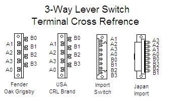
Here is a switch cross reference chart:

3way_lever_switch_cross_refrence.jpg

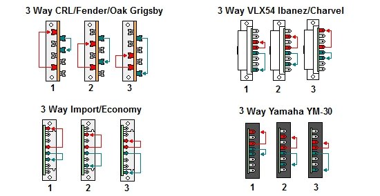
And a connections chart:

3way-lever-switch-terminal-connections.jpg
 
Last edited:
Re: Blackouts wiring help

Also, in your photos: what is the loose hanging red wire, the one that disappears into the body, connected to?

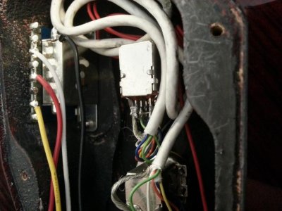
Here is how the switch in my Hellraiser (with EMG 81tw and 89r actives) was wired: (link if pic doesn't load)

20141029_111549.jpg

Notice that the Yellow wire on the switch is connected to lugs B2+B1 (neck pickup input), the Red wire is on lugs B0+A0 (signal output to vol/tone), and the White wire is connected to lugs A3+A2 (bridge pickup input).

Do you know how to solder? If so, you should re-wire the switch to match this (with 22awg, 24awg, or 26awg insulated wiring) and then ground the pickup ground wires to the ground star. Use at least a 40watt soldering iron, and not a soldering gun..
 
Last edited:
Re: Blackouts wiring help

It’s not showing the attachment. I’ll try what you said, I actually don’t know what the red wire is connected to
 
Re: Blackouts wiring help

Awesome, thank you, I think I see what’s wrong. In the diagram that SD supplies, it’s made to look like one wire is running through 4 points on the switch, so that’s actually what I did. I’ll post back as soon as I can.
 
Re: Blackouts wiring help

Awesome, thank you, I think I see what’s wrong. In the diagram that SD supplies, it’s made to look like one wire is running through 4 points on the switch, so that’s actually what I did. I’ll post back as soon as I can.

Well both ways should work the same, electrically, I just always see import lever switches wired the way it is wired in my posted image. Regardless, the signal wire needs to be insulated (even if you use masking tape it will work better than what is currently there) and the pickups need to be properly grounded.

Do you know how to solder?
 
Re: Blackouts wiring help

Yes, I have an Aoyue soldering station with fine point soldering gun, soldering vacuum and heat controls. However I am definitely an amateur. If you have any advice or suggestions that would be great. The wire is not insulated because I figured the best way to get the wire through a serpentine like configuration would be to bare it and run it through the points. I used to solder a lot back in the day but it was just mostly pot replacement or light maintenance, it was never anything like full rewiring with active pups.
 
Re: Blackouts wiring help

Success. Thank you for your help. These pups give the extra crunch I was looking for.
 
Back
Top