Re: Can someone please explain inductance to me in simple terms?
Inductance can not be explained in simple terms other than to say that it is "That property that opposes a change in current."
The amount of opposition to an AC signal through a coil is called Inductive Reactance. It is measured in Ohms, just like a resistor.
If you wind a bunch of turns of wire around a steel core, the current thru the wire will generate a magnetic field. According to Lenzs Law, the polarity of that field will be orientated in such a way as to push back against the voltage that is generating it. The voltage finally wins, but that opposing mag field keeps current from flowing thru the inductor until the voltage is at a max and the mag field is no longer increasing, and therefore no longer opposing a change in current. When the mag field begins to collapse from a decending voltage, it does so in a way that increases current thru the coil. It induces a voltage into the winding that causes the flow of current. So when the voltage is rising, the inductance keeps the current from rising with it. And when the voltage is going down, the inductance keeps the current from dropping. The net effect is that the current will be smoothed out. This is what a smoothing choke does inn a power supply.
The formula for Inductaive Reactance is XL = 2 pi f L where 2 pi = about 6.28, f is frequency measured in Hertz, and L is the amount of inductance in Henrys.
Example Calculation: Coil: 10 Henries Frequency: 10 Hz. What is the Reactance or Resistance to the AC signal of 10 Hz?
Easy. XL (Inductive Reactance) = 6.28 * 10 Henries * 10 Hz = 6.28 * 100 = 628 Ohms.
So if you had, lets say, a 1 Volt signal at 10 Hz in series with a 10 Henry coil, the current through the coil would be 1/618 = 0.0016 Amperes. (Using Ohms Law E = IR)
So once you know your Reactance in Ohms, you can use it just like a resistor in the Ohms Law formula.
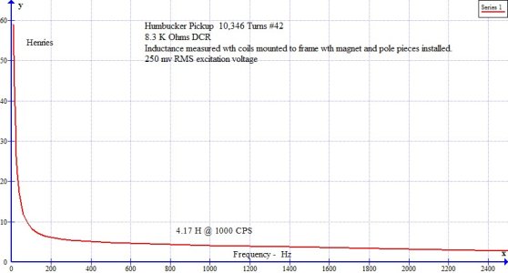
Now this is where things get interesting. Reactance, if you look at the formula, depends on frequency. So the resistance to an AC signal from the coil is non linear. It will go up as the frequency goes up.
So lets say you hit a low A note on your Les Paul. That 10 Henry coil will offer up about 6.28 * 110 Hz * 10 H = 6900 ohms of resistance. This is the resistance that the signal will be developed across in the pickup coil. Now if you play an A note an octave above your low A, you will have an XL of 6.28 * 220 Hz * 10 H = 13,800 ohms, or twice that of the reactance you had with the low A.
This means that if you hit a very high note, like an A up on the 17th fret, 880 Hz, you will be developing your guitar signal across a resistance of 6.28 * 880 Hz * 10 H = 55,000 Ohms, or 55 K Ohms if you like. This means that very little current will be lost through the coil and that as a result, most of the string energy will be transmitted to the guitar amp.
As luck would have it, your bass strings are thicker than your treble strings, so they generate more signal on the pickup when they cut across that magnetic field of the pickups, so things tend to balance out, the bass notes put out more juice than the trebles, but more of that juice will be needed by the pickup coil to give you the same voltage output as a treble string, because the Reactance of the coil is lower at bass frequencies so more current will flow through the coil. At treble frequencies, the small .010" string will not generate as much signal, but less will be lost through the coil as the reactance of the coil goes up with frequency.
So pickup makers can tweak the frequency response of the pickup by changing the inductance, or Henries of the coil. More turns means more inductance, which means less loss at the bass frequencies. Less turns will mean a brighter coil as you will lose bass energy due to the ohms of the pickup being lower due to less inductance. Note that inductance goes up with the Square of the turns. So if 100 turns = 1 Henry, 200 = 4 Henries. (2/1 = 2, then 2^2 = 4)
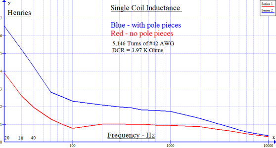
But the fun does not stop there. Since there is metal inside the coil in the form of slugs and pole pieces, you have what amounts to an iron core inductor. With that comes a whole new list of formulas and mathematical models that will fill a good sized text book. These formulas deal with such things as complex currents, (j operators for all you propeller head math freaks), B-H loops associated with the type of metal used in the pickup, core saturation, (of which there is not much due to the low signal levels involved in pickups), distortion, phase shift, frequency response, excitation current ( the steel parts steal current to get their magnetic molecules moving) , Q, resonance, and a litany of other factors that almost make experimentation in the lab an easier way to find the sound you are looking for.
You hear about larger pole pieces and slugs for a stronger field near the strings as to increase signal. Does that do anything to your waveform? Excitation current is non-sinusoidal. The more metal, the more excitation current in the coil which gets combined with the sine wave of the guitar signal. Does this actor affect tone? I do not know, maybe someone else has done experiments in this area but it may be something to consider.
Does the fact that the current in an inductor lags the voltage by 90 degrees make any difference to pickup winders? Not really. So don't worry about that.
Now the metal parts in the pickup increase the inductance of the pickup coil by concentrating the magnetic lines of flux generated by the moving guitar string, but not to the extent of say, a guitar amp output transformer. So what you really have is an air core inductor with a small core inside, so a lot of the math associated with a steel core inductor might not need the consideration the get when designing a transformer.
There is another part to the story of pickup inductance, and that is capacitance. A capacitor is formed by two conductors separated by an insulator. So if you lay two pieces of #42 pickup wire side by side, you will have formed a capacitor, albeit a small one. Maybe only a few pico farads for say, a 1 meter length. But there is a lot of wire in a pickup. So you develop tiny capacitors between turns, slightly larger capacitors between the layers of wire, and you will also have capacitance between the coil and metal parts that are grounded, such as the pickup covers, etc.
So there is a limit to the number of turns you can use before the sum of all this capacitance starts to rob your guitar signal, especially the high end. Capacitance Reactance (resistance to AC signals) goes down with frequency, (the opposite of inductive reactance) so the higher the guitar note you hit, the more signal you lose to stray capacitance.
Now when you add the math of coil capacitance to the math of the coil inductance, you really have a puzzle on your hands.
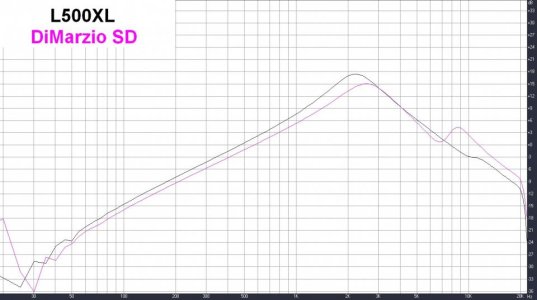
This is because the inductance of the coil and the capacitance of the turns will form a resonant circuit. This happens at a frequency where the inductive reactance equals the capacitive reactance. This is what causes that peak you see when pickups are swept for frequency. So you can tweak a coil to get that resonant peak where you want it by adjusting turns to vary inductance and capacitance at the same time. It is a balancing act, so to speak.
But there is more! That magnet wire has resistance. When resistance, inductive reactance, and capacitive reactance are combined, you have what is called Q. This is the ratio of the coil reactance to the DC resistance, or DCR. This Q factor will affect the shape of the resonant peak. The more DCR, the flatter the peak. So now you have another variable to play with, wire size. Smaller wire will have more ohms per mile than big wire. So the bigger the wire, the sharper the peak. But remember, we need a lot of turns to get the Henries we need for these air core inductors, so we are limited as to our wire size. You can only get so many turns of #42 on a bobbin.
DCR also affects the bass frequency response in the form of phase shift. Now I am not too sure as to the exact effect this has in pickups as I am mostly a transformer geek. But in a transformer, degrees of phase shift between the input signal on a transformer primary and the output on the secondary is computed by Arctan DCR/XL. But really all you need to know is that the more DCR, the bigger your phase shift at the lower freqs.
And one last thing. Wire Size. I see a lot of talk about wire size and pickup DCR. But what I do not see is a lot of talk about wire size and capacitance. When you use #43 instead of #42 to wind a pickup, you can get a hotter pickup because you can fit more wire on there with the smaller #43. But with more turns comes more capacitance, right? Well kind of. The amount of capacitance of a capacitor is determined by the size of the plates and the distance between them. So using a smaller wire means less capacitance due to the fact that the diameter of the copper is smaller. So by using smaller wire, you can actually decrease your high end loss due to the fact that there is less metal to short out your signal. Now you can also vary this capacitance by your winding technique. Scatter winding puts more air in the coil, that is, you have more distance between turns as you have wire crossing over each other instead of laying side by side, and thus less capacitance than a nicely layered CNC winder as you are increasing the distance between the plates of the capacitor (copper wire turns) . So now you have another variable to play with, hand wound vs machine wound. And smaller wire will lay latter than big wire, so you have another factor there as a flatter lay will mean less distance between the "plates" of your stray capacitors.
Thus, a big balancing act between variables, change one thing and you change another. And that is just the coil. Throw in the properties of different magnets and you have yourself a lifetime full of fun!
Last edited:

