Can someone please explain inductance to me in simple terms?

Re: Can someone please explain inductance to me in simple terms?

Pico is right, I made it sound like using tape was as good as sectioning and that is incorrect and for that, i apologize.

There are two different things going on in that post, sectioning, and using tape to increase the distance between layers.
The tape thing will reduce capacitance, but not as effectively as sectioning.

The formulas for winding capacitance are quite cumbersome and can only give an approximation as to total C. In the end, the ears are the final judge.

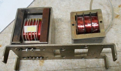
Here is a look at an example of sectioning on a V72 input xfmr and a plate choke. The input transformer has 2 primaries and 4 secondaries. Original transformers used pre-wound discs that were slid over a phenolic bobbin, a process that was quite tedious.
On this rewind, we used 4 wires at a time to build up the secondaries while using spacers or the primaries, which were wound after the secondaries. tele.JPG
 
Re: Can someone please explain inductance to me in simple terms?

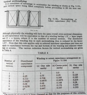
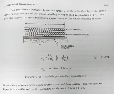
Here is a page out of RDH4 (Radio Designers Handbook Version 4) on sectioning.

Note that you can simulate this section process while winding a pickup, instead of going back and forth with your winding machine, you build up "pies" on the bobbin by staying in one place for a while and then moving on. This is often done while winding torroid coils which can have a lot of leakage C. Jensen Transformers uses this technique on some of their audio transformers.


r1.JPG
 
Last edited:
Re: Can someone please explain inductance to me in simple terms?

Hmmm. Now, from what I've heard, Fishman is doing something with printed cores or something like that...
 
Re: Can someone please explain inductance to me in simple terms?

Fishman? I believe it. If they are using more turns than an electric pickup, then capacitance will start to be a real problem. They probably want to preserve the high end of the guitar, and harmonics can go way above the fundamental frequency.

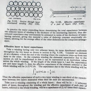
Here is the info on the other capacitance reducing technique with the tape. Guitar pickups do not use inter-layer insulation like transformers, as there is a very low voltage gradient from layer to layer. So the distance D between layers in determined by the winding technique and the thickness of the wire insulation. It would be interesting to find out how thick the enamel insulation was that was used on the original PAFs.

r2.JPG
 
Last edited:
Re: Can someone please explain inductance to me in simple terms?

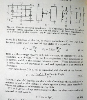
Don't like solving integrals that much, (forgot how!) so there are other approaches that do not involve calculus.

Note fig. C in the drawing. This is a winding techniques used for example in the UTC A-10 mic input transformer (used in the famous LA2a audio limiter/compressor) which has about 8,000 turns on a pair of coils. It is called "foldback" winding. This means that after finishing a layer, you do not go back in the opposite direction with another layer. Instead, after finishing a layer, you take the wire back to where you started with a turn or two, and start another layer. What this does is cut down on the voltage gradient between the ends of the layers. This has the effect of reducing layer to layer capacitance. This technique can be used for winding pickups two. You could easily program a modern winder to do this or do it while hand winding.

I have noticed the pickups i have taken apart have the finish of the windings of both coils joined together and that starts go to ground and the pickup switch. What this does is move the highest voltage gradients away from each other as they are buried beneath the other turns. Since the two coils are close together, your low voltage center tap will be the outside layers and thus will not interact as much as if the outside layers had the maximum voltage between them, although we are only talking about 100 miilivolts or so. Having the finishes as the CT might also act as a shield against outside EMI, keeping the business end of the coils buried under the copper wire.

g1.JPG
 
Last edited:
Re: Can someone please explain inductance to me in simple terms?

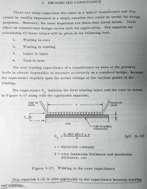
And another look at this from Col. McLymans book which probably has the most workable equations.

Note: MLT stands for Mean Length Turn which is the average length of all the turns of the pickup, example - inner turns are 5 inches, outside turns are 6 inches, so the MLT is (5 + 6) / 2 = 5.5".


Single layer capacitance>l1.jpg
 
Last edited:
Re: Can someone please explain inductance to me in simple terms?

And finally the formula for capacitance for all the layers>

Note: Cc must be derived from the previous page.

l2.JPG
 
Re: Can someone please explain inductance to me in simple terms?

Could I suggest that this thread be vaulted? After some more discussion of course. This thread is really interesting and educational, especially because it started out in simple terms and progresses slowly to propper high level electrical terminology.
 
Re: Can someone please explain inductance to me in simple terms?

I'm not saying it's wrong, but I'd think you'd want to have the information vetted a little before suggesting it be pinned.
The lists of formulas alone make this a valuable thread, and even if some of the theory is off (and I don't think it is), the underlying concepts can be checked online.

Again, I hope a moderator will preserve, but I'm copying the thread for myself to anotate and organize my thinking.


Sent from my SAMSUNG-SM-G920A using Tapatalk
 
Re: Can someone please explain inductance to me in simple terms?

Hmmm. Now, from what I've heard, Fishman is doing something with printed cores or something like that...

I believe the Fishman Fluence is a low impedance with a purely simulated resonance, so capacitance probably isn't a problem anyhow. I saw probably low impedance, because I really doubt they're achieving 8,000 turns with a stack of printed surfaces, or even coming anywhere close.
 
Re: Can someone please explain inductance to me in simple terms?

Here is a page out of RDH4 (Radio Designers Handbook Version 4) on sectioning.

Note that you can simulate this section process while winding a pickup, instead of going back and forth with your winding machine, you build up "pies" on the bobbin by staying in one place for a while and then moving on. This is often done while winding torroid coils which can have a lot of leakage C. Jensen Transformers uses this technique on some of their audio transformers.


View attachment 88500

Thanks for taking screen shots of the book. This does go to show that how the pickup maker lays the wire will have some effect on the capacitance, though unless they deliberately create these sections, the coil will not have a sectional structure overall. The best you could do is sort of create little "piles" like you said. The biggest caveat though is "note this rule refers to inter-layered capacitance" which will be some fraction of the overall capacitance. I think in order to realize a real savings on capacitance, the coil would have to have physical walls, so that the sections could be fully maintained.

Given the standard production methods of guitar pickups, I think their best bet for reducing capacitance is getting the thickest insulation possible with the lowest dielectric constant available. It would be interesting to see information on these fronts. I've seen really high capacitance with Telecaster neck pickups, and I'm curious to know if they use especially thin insulation in order to keep the coil small.

Also note, regarding core-to-coil capacitance, that will be a thing with humbuckers that have grounded screws and poles, but not for Fender single coils that have ungrounded AlNiCo poles. The coupling beteen the screws will be smaller than for the slugs of course, but there is a small amount of space between the windings and core regardless, due to the thickness of the plastic bobbins. In any case, the core to coil capacitance is a lot smaller than the inter-coil capacitance, so it can mostly be neglected. For example, take a humbucker, un-ground the chassis, you won't hear much difference. The capacitance is more noticeable with Joe Barden blade style humbuckers, though, where the blades are grounded and represent a substantial solid steel core, which is also very close to the coil windings.

BTW, Colonel. McLyman is 85 years old now, but still going aparently. I wonder if he still thinks about any of this stuff.
 
Last edited:
Re: Can someone please explain inductance to me in simple terms?

Could I suggest that this thread be vaulted? After some more discussion of course. This thread is really interesting and educational, especially because it started out in simple terms and progresses slowly to propper high level electrical terminology.

Glad I managed to accidentally start something useful! Honestly this thread is mostly over my head now and well beyond what I wanted to know but for some reason I am still enjoying reading it.
 
Re: Can someone please explain inductance to me in simple terms?

Hi Dave! A simple bottom line answer to your question is increased inductance means more bass. And probably more output, depending on magnet strength. Of course this is a generalization as there are other factors involved.

I am just getting started in the pickup thing, so at this point, i am just fishin and fumblin, throwing out ideas, trying to find my way, hoping someone with knowledge will call me out when making mistakes, but i am making progress.

With all the different rez curves and sounds of different model pickups, i wonder if the guitar cord is really going to swamp all that out. I am thinking that the cord has to be analyzed as a transmission line, that is, a cord will have inductance and capacitance, and thus, propagate the signal a little more efficiently as it can be thought of as a wave guide.

Just learned i need to insert a 1 Meg resistor in the sig gen line to simulate a guitar string which acts as a constant current source rather than a constant voltage source, (Hi Z) and that I need to plot Impedance, not Inductance to see what a pickup is doing,

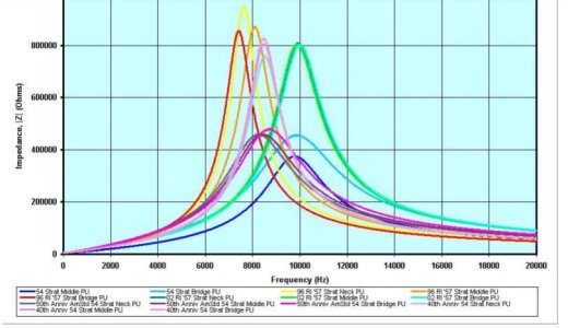
This wonderful article right here, now this should go into the vault, whatever that is>

http://www2.ece.rochester.edu/cours...oject/Electric_Guitar_Pickup_Measurements.pdf

Scroll down for charts like this>

pickup.jpg
 
Last edited:
Re: Can someone please explain inductance to me in simple terms?

With all the different rez curves and sounds of different model pickups, i wonder if the guitar cord is really going to swamp all that out.

In my own World, the answer is no. Examples:

-When a pickup promotes selectively some high frequencies, even above 10khz, it can be heard. I had once to “correct” a (non typical) design creating a secondary resonant peak around 11 or 12 kHz : it was generating a buzzing "drone" sound, unnatural and even painful to hear through a clean bright amp like a JC120 or a Fender Twin.

-@ the same inductance, it’s not the same to play a pickup with a stray capacitance of 100pF through a 500pF cable and a 200pF coil through a 400pF cable. Although the overall capacitance stays at 600pF and would dictate a same resonant frequency (for a same inductance) when controls are full up, pickups with low and high stray capacitance behave differently when the volume pot is lowered.


I am thinking that the cord has to be analyzed as a transmission line, that is, a cord will have inductance and capacitance, and thus, propagate the signal a little more efficiently as it can be thought of as a wave guide.

FWIW, here is how the "sweet switch" designed by PRS modelizes a huge lenght of cable : https://forums.prsguitars.com/threads/how-a-sweet-switch-really-works.839/

Here are the specs of the delay line used by PRS to do that : http://www.datadelay.com/datasheets/1513.pdf

And for other readers, here is a link possibly useful to understand why PRS uses a delay line to emulate a long cable ; https://www.st-andrews.ac.uk/~www_pa/Scots_Guide/audio/part7/page1.html

... and thx for sharing, cjenrick! :-)
 
Last edited:
Re: Can someone please explain inductance to me in simple terms?

Hi Dave! A simple bottom line answer to your question is increased inductance means more bass. And probably more output, depending on magnet strength. Of course this is a generalization as there are other factors involved.

I am just getting started in the pickup thing, so at this point, i am just fishin and fumblin, throwing out ideas, trying to find my way, hoping someone with knowledge will call me out when making mistakes, but i am making progress.

With all the different rez curves and sounds of different model pickups, i wonder if the guitar cord is really going to swamp all that out. I am thinking that the cord has to be analyzed as a transmission line, that is, a cord will have inductance and capacitance, and thus, propagate the signal a little more efficiently as it can be thought of as a wave guide.

Just learned i need to insert a 1 Meg resistor in the sig gen line to simulate a guitar string which acts as a constant current source rather than a constant voltage source, (Hi Z) and that I need to plot Impedance, not Inductance to see what a pickup is doing,

This wonderful article right here, now this should go into the vault, whatever that is>

http://www2.ece.rochester.edu/cours...oject/Electric_Guitar_Pickup_Measurements.pdf

Scroll down for charts like this>

View attachment 88533

More inductance itself doesn't get you much more bass, you can see it in the plot in your post. Notice how the impedance barely changes between 0 and 2,000Hz, and doesn't begin to substantially vary until it reaches near the resonant peak?

Inductance will track with output only because the more wire you add, the more voltage you generate, and the higher the inductance becomes. The two increase in tandem, but one does not cause the other. For example, if you were to simply put an inductor in series with the pickup, it would not increase the lower frequncies, it would merely decrease the high frequencies, and that's what the added inductance of a guitar pickup causes to happen.

Regarding cable capacitance, since the volume control is set up as a voltage divider, as the volume is turned down, increasing resistance shows up in series with the capacitance of the guitar cable. Therefore, as the volume is decreased, the resonance frequency of the pickup increases, but the Q factor drops, causing the pickup to sound darker overall, giving rise to treble bleed circuits or the "50's wiring" mod.
 
Last edited:
Re: Can someone please explain inductance to me in simple terms?

Good points! ^^^

We found some more cable talk at a studio forum>

> can the coax be thought of as a wave guide, ie: inductance and capacitance distributed along its length as to not cause as much loss as your C meter reads for a 10 ft section?

"Keep going on that thought and you will re-derive the Telegrapher's Equation, about 130 years too late for fame.

But for a start: put numbers on that thing! How much inductance does an audio cable have?? While not quite Guitar Cable, 8451 will be close-enough to know if we need more exact numbers from a specific cable.

Belden 8451 cable
Conductor DCR 14.1 Ohm/1000ft
Capacitance Conductor to Conductor 34 pF/ft
Capacitance Conductor to Other Conductor to Shield 67 pF/ft
Inductance 0.17 µH/ft

One foot at 0.17 µH/ft at 20KHz is 0.17uH*20KHz*6.28 which is 0.021 Ohms. Ten feet (3m) is 0.2 Ohms. 100 feet (30m) is 2 Ohms.

Compare with the C. 67pFd at 20KHz is about 120K. Ten feet makes 12K, 100' makes 1.2K.

An ignorant approach would lump all this together. For 100 feet we have 2 Ohms inductive series reactance and 1,200 Ohms shunt capacitive reactance.

Clearly for most likely line impedances, the 2 Ohms of L "does not matter", the 1,200 Ohms of C might.

However driving a 4 Ohm speaker, 2r inductance hurts the top significantly.

This points to the idea of "Characteristic Impedance". The line has both series and shunt losses. The split-difference between them is the best impedance to work the line. You can't measure this directly, it is the value which gives best results. The characteristic impedance of about any practical line will be 50 to 200 Ohms. For short good lines you can go way off this without much added loss. Go high, and you are looking into significant Capacitance. Go low, and you fight both Inductance and the cost of low Copper resistance.

The values of L and C are set by conductor dimensions and adjacent materials. We could raise L by adding iron; this usually "bad" so is rarely done. We can raise C by using solid materials to support the line conductors, or lower C with only vacuum (or gas) dielectric. Because the conductors do need support we are usually sticking solid stuff in there. Minimum C might be the old open-line telephone wires. Mostly we value a tough cable so PE plastic is common. For lower C we can use foam plastic, or spaced ceramic disks.

In fact we should solve for an infinite number of infinitely small L and C. But if you try this, you generally find that it is "no real difference" as long as the line is "short" compared to the wavelength. Audio in a wire travels a little slower than the speed of light. It takes 8250 feet (2500m) to make even a quarter-wave at 20KHz. In "studio audio" we never go to such lengths. Lump-sum approximations are close-enough.

OH!! A full derivation includes plain Resistance, both series and shunt. 1,000' of 8451 is R=14r and L=20r @ 20KHz. This makes a small difference, negligible on line impedance though significant on speakers. The shunt resistance of modern plastics is super-high for DC and well into the audio range. Typical may be G @ 10KHz 0.16µS/1000 ft which is 6 MegaOhms

And for guitar specifically: there's like 5 Henries in a guitar pup. Another 29,411,765 feet (5000+ miles!!) of that 0.17µH/ft Belden cable would matter some; less, hardly at all."

Equations for transmission lines, watch out! Hyperbolic trig functions and Diff equations abound!

https://en.wikipedia.org/wiki/Telegrapher's_equations
 
Re: Can someone please explain inductance to me in simple terms?

You lost me; what part of that did you intend to related to guitar pickups?
 
Re: Can someone please explain inductance to me in simple terms?

The post relates to guitar pickups vs guitar cords.
 
Re: Can someone please explain inductance to me in simple terms?

OK, well the capacitance of the cable does lump with the pickup, it can be assumed to be anywhere from 200nF on the low end to 1nF on the high end. A coiled guitar cable, like Hendrix used, can reach 3nF. The series inductance of a guitar cable is miniscule. This is one reason why inductance measure of a pickup is so important, of L and C, only L follows the pickup wherever it goes.
 
Back
Top