Capacitor for partial coil split

andyg_prs

New member
Hi,

My old PRS CE24 long since lost its rotary switch and has a traditional 3 way switch with a push push for coil splitting. One pickup split to hot, one to ground.

I love the coil split sound but the volume drop is too great live. So I wired each pickup to a 10k trimpot, and I'm playing around trying to find the balance of not too much volume difference with the split position not sounding too full.

What I think will improve things is somehow losing some of the bass signal from the partially split coil.

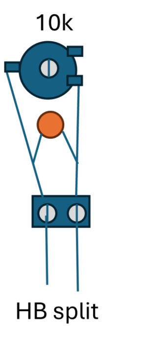
I think I could do it with a capacitor wired like this - just shown for one of the pickups. I already have a small board built for this, am just adding the capacitor.

Split with Cap.png

But, 1. is this correct? and 2. any idea what sort of capacitor values I should consider? I'd rather start with a lot of bass loss and then be more subtle if needed.

Thanks,
Andy
 
Actually I think I'd need a capacitor between the two humbucker coils, but the trouble is, PRS only present a single 'split wire' so I don't think this is possible......
 
ive never tried to add a cap to a partial split before, curious how you make out.
 
Actually I think I'd need a capacitor between the two humbucker coils, but the trouble is, PRS only present a single 'split wire' so I don't think this is possible......

While it would do the contrary of what you want by bumping the bass, you can still put a capacitor to ground at the junction between coils, emulating a "fat tap" wiring.

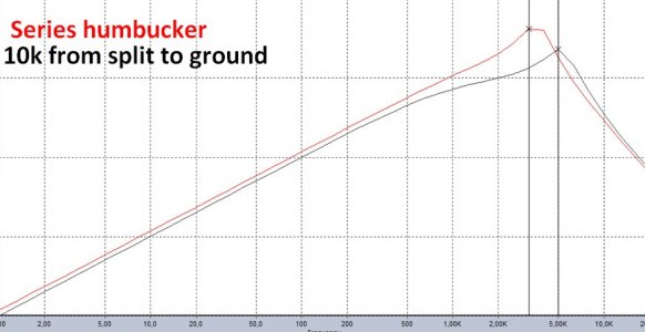
Below is the Sspice emulated resonant peak of a humbucker in series vs with a 10k resistor from hot to ground, disabling partly the first coil, as you've apparently done it.

SplitCoilResistor.jpg


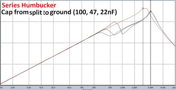
Now, below is the same thing with caps instead of the 10k resistor. As expected, it's as if the first coil had a tone control at 0/10 instead of being totally disabled, while the second coil works normally... Putting the same caps in parallel from ground to split with the first coil (the grounded one) would hardly change these curves.

SplitCoilCapacitor.jpg

And putting a resistor in parallel with one of these caps would simply make less drastic the related peaks + dips ...


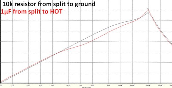
ALL THAT BEING SAID, what Would happens with a 1µF capacitor (yes, it's a huge value) from split to HOT?

Theoretically, this:

SplitCoilCapToHOT.jpg Scooped response from 50hz to resonant peak, wich becomes pointier... Hence a brighter tone, normally.

Might be something to try, albeit my memories are not fresh when it comes to define if it would increase HF noise in an annoying way or not (I've already toyed with such wiring and components but my brain is too old to memorize the countless lab results collected here the last decades during similar experiments)... :-P

HTH anyway. :-)
 
As I can't edit the previous answer without getting an error message, here is an ERRATUM. Before the first pic, please read "Below is the Sspice emulated resonant peak of a humbucker in series vs with a 10k resistor from SPLIT to ground, disabling partly the first coil, as you've apparently done it" (and not "from hot to ground", which would make the output level of the pickup terribly low, obviously. :-P)...
 
freefrog - I'm immensely grateful but feel quite humbled by your knowledge - and my lack of it!

In your first diagram where you are showing what I have done with the trimpot, I assume the Y axis represents the volume / strength of signal. I'm surprised the volume doesn't show a greater drop off....but also, at least to my ears.....the higher the resistance...winding the trimpot from 0 - 10kohms....it feels like it's getting bassier, but that could just be how my ears interpret it....but the resonant peak seems to have moved from 3.5 to 5k? I assume the higher the frequency of the resonant peak, the more trebly the overall sound?

In the second diagram the resonant peak of one of the same coil is in the 300 - 700hz range and hence you describing that as rolling the treble control completely off on one of the coils?

In the last diagram, you have the much higher value capacitor but taking it to hot. And that has that higher peak which makes it brighter. I'm trying to understand why though? Also, if there is no drop in output, isn't it just going to sound like a more trebly humbucker, rather than sounding a bit single coil like? So I'd still have to have a resistor in there somewhere....but I don't know where?

If you could please explain, I'll try to mock up another diagram to see if it makes sense.

Thanks again!
Andy :)
 
freefrog - I'm immensely grateful but feel quite humbled by your knowledge - and my lack of it!

You're welcome, Andy. Always glad to help.

In your first diagram where you are showing what I have done with the trimpot, I assume the Y axis represents the volume / strength of signal. I'm surprised the volume doesn't show a greater drop off....but also, at least to my ears.....the higher the resistance...winding the trimpot from 0 - 10kohms....it feels like it's getting bassier, but that could just be how my ears interpret it....but the resonant peak seems to have moved from 3.5 to 5k? I assume the higher the frequency of the resonant peak, the more trebly the overall sound?

About volume: my 5spic sim mimics the electrical behaviour of coils submitted to a constant stimulus. Playing the pickup would aggravate the difference by sending transients to it.
About the EQing: yes, the resonant peak of the half split PU is higher pitched, translating one of the main differences between coils in series/humbucking mode and single coil/ split coil.
But as you can see, the resonant peak "sags" progressively beyond 500hz. A bit as if a tone control was lowered... and with a potential influence on the perceived volume.

In the second diagram the resonant peak of one of the same coil is in the 300 - 700hz range and hence you describing that as rolling the treble control completely off on one of the coils?

With a capacitor from split to ground, the first coil sounds as if it had a tone control completely turned off. The second coil keeps resonating normally at high frequency. My pic shows the combination of both, illustrating the Gibson "fat tap" principle (one coil promotes the bass and low mids, giving its fatness to the other).

In the last diagram, you have the much higher value capacitor but taking it to hot. And that has that higher peak which makes it brighter. I'm trying to understand why though? Also, if there is no drop in output, isn't it just going to sound like a more trebly humbucker, rather than sounding a bit single coil like? So I'd still have to have a resistor in there somewhere....but I don't know where?

The overall output drop in this case is not worse than with the 10k resistor but the pointier resonant peak might make the sound more realistic and more alive.
The high value capacitor in parallel with the coil almost totally bypasses it but not totally since it's a cap (which is nothing else than a frequency dependent resistor, to keep it simple). A lower value cap at the same place (from split to hot) would generate roughly the same kind of response than in pic 2, if memory serves me.
A resistor in SERIES with the cap would limit its action. The whole (resistor + cap in series) would be placed in parallel with the coil going from split to hot... If it was for me, I'd probably use a mini 10k trim pot for that... And I wouldn't hesitate to try the resistor alone in parallel with the second coil from split to hot. :-)

If you could please explain, I'll try to mock up another diagram to see if it makes sense.

Hope it's clearer now. But what I've shared is just 5spice simulation meant to give "an idea" of what happens. As I said, the related experiments are too far in the past to be remembered by my old brain.

So IMHO, the best thing to do in such a case is to try different wirings with a few alligator clips. I always end doing that myself. Sometimes it sounds good, sometimes not. Depends on the specs of the gear used (including the location of coils under the strings). Which makes my sims not that useful finally. Reason why they were shared humbly as well. ;-)

Good luck in your experiments. Keep us informed. :-)

FF
 
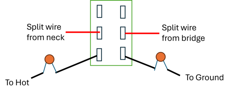
​Thank you so much! First pic - push push pot - the original coil split had the bridge split going to hot and neck split going to ground.


corrected original split1.png
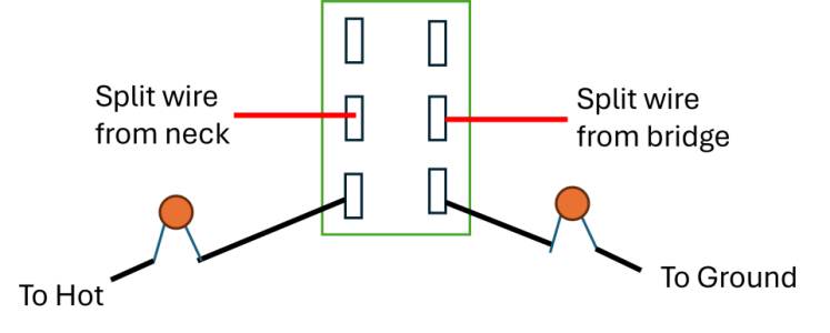
Second pic - if I have understood correctly to get the capacitor in series, I need to wire like this. Is that correct?

corrected cap split.png
 
Last edited:
Thank you so much! First pic - push push pot - the original coil split had the bridge split going to hot and neck split going to ground.


Second pic - if I have understood correctly to get the capacitor in series, I need to wire like this. Is that correct?


Maybe I'm too tired right now, but I fail to understand your pic...

The horizontal blue lines between upper poles make it look as if the split junctions were connected to each other when the push-pull is up, which would give a very unusual combination...

With the push-pull down, I'd try the cap connected to hot AND ground for each pickup before to decide and I'd experiment with a vast array of capacitive values. I'd also toy with various resistors (or trim pots) in series or parallel with (or instead of) each cap, just to be sure.

Do what you want and keep us informed anyway. Good luck in your tonal experiments. :-)
 
Ah, so sorry, that's my mistake.....there is no wire at all....not enough coffee! Corrected my original post and here:

corrected original split1.png

corrected cap split.png

However, with that push push pot wiring....I'm not clear how I would achieve what you are suggesting (I'm sure a professional could completely rewire to do that..)

Is there a way to achieve that or similar with the starting point of the push push pot I have shown? (I find push push much easier than push pull but they do fail occasionally)
 

Attachments

  • photo113950.png
    photo113950.png
    20.4 KB · Views: 0
Yeah, the pics make sense to me now and I've got you use push-push pots. :-P

Regarding how to do what I've said: IF you want to experiment, order online 5 cables with alligator clips and an assortment of non polarized capacitors (plus a box of low voltage resistors if needed)... It shouldn't cost you much money.

Then put two cables with alligator clips on the bottom lugs of your push-push pot. Two other cables on the hot terminals of your pickups. One alligator clip to ground. Try different combinations from lugs to hot or from lugs to ground, with different capacitors in between... If you want a fat tap wiring, try the capacitive values mentioned in my screenshots, which are also regular tone caps values (100nF= 0.1µ, 47nF=0.047µ, 22nF=0.022µ). If you want less fatness, rise the value of the cap(s) used (up to 1000nF=1µ if necessary, albeit I'm still not sure it's a good idea. I'll have to check that with a real humbucker and a real cap in the next days, if time permits )...
Oh, and compare with your 10k resistor trick in each case.
Once it sounds to your liking, remove the alligator clips and solder the components used instead. It shouldn't take a too long time.

HTH,

FF
 
Ah cool, at first I thought you were saying to take the split to hot and ground at the same time which confused me :)

So, if the split wire on the neck goes to ground to cancel the second coil, I'm assuming we have this (standard coil split):

pickup basics.png

Because the split has gone to ground, it doesn't pass through the second coil.

Revisiting your original explanations (sorry), if I put the split to ground via a capacitor, as per your second graph, the treble frequencies bleed off the first (top) coil and so it's like a tone control a zero....I get that....but then you said the second coil resonates normally. I don't understand how the second coil can sound normally.......either no signal gets to the second coil....as the signal has gone to earth via the split via the capacitor....or maybe do the bass frequencies that got blocked by the capacitor make it to the second coil? But then that coil would sound bassier?

I think I'll try to understand that first before trying to figure out what happens when the split is taken to positive hot :)
 
It won't let me edit above....for Because the split has gone to ground, it doesn't pass through the second coil.....I meant to say - Because the split has gone to ground, no signal passes through the second coil. - literally the path of least resistance :)
 
I don't understand how the second coil can sound normally.......either no signal gets to the second coil....as the signal has gone to earth via the split via the capacitor....or maybe do the bass frequencies that got blocked by the capacitor make it to the second coil? But then that coil would sound bassier?

I think I'll try to understand that first before trying to figure out what happens when the split is taken to positive hot :)

I've said that the second coil behaves "normally" because it resonates at the frequency due to its inductance + the parasitic capacitance of the wiring... But it was a simplification in order to be clear.
Actually, here is what happens with a cap from split to ground:
-the first coil sees its capacitive load drastically increased by the capacitor (how surprising). So it resonates at a very low frequency. That's what happens to any pickup with its tone control at zero.
The second coil is partly fed by the first coil (until the resonant frequency of this first inductor) then behaves as if it was linked to ground through the capacitor. IOW: as if it was grounded through a series cap, which would make it tighter (with a "bass-cut" / hi-pass filter effect) if there was no first coil to give it its bass... :-D

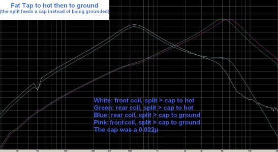
A quick search in my archived data made me find an old forgotten test shared below. It shows how the two coils of an humbucker resonate with a 22nF cap @ their splitting junction, in 4 possible wiring configurations...

It's an actual measurement made here on a real pickup, magnetically excited. The difference with my 5 spice sims is that the resonance of each coil can be seen separately (while a 5spice sim combinates the two curves in a single one).

Maybe it will make clearer what happens with the "Fat Tap" thing (causing a dip @1500hz in this case, between two peaks at 550hz and 5/6khz respectively: so the sound remains beefy in the bass and low mids, while being brighter than in series humbucker mode).

FatTap&RevFatTapRevResized.jpg
 
To precise my previous reply, that I can't edit without error message:

With a capacitor at splitting junction...

...the first coil sees its capacitive load drastically increased by the capacitor (how surprising). So it resonates at a very low frequency. That's what happens to any pickup with its tone control at zero.
The second coil is partly fed by the first coil (until the resonant frequency of this first inductor) then increasingly behaves as if it was linked to ground through the capacitor, which progressively relays the first coil. IOW: at high frequencies, it's as if it the 2d coil was finally grounded through a series cap, which would also make it tighter (with a "bass-cut" / hi-pass filter effect) if there was no first coil to give it its bass... :-D

 
Thanks so much. I'm still processing and don't fully understand - I wish I'd studied electronic engineering rather than genetics. But I will do some testing once childcare allows and report back :)
 
Back
Top