Challenge! Wiring Diagram HSH

** BUT if Artie comes through on successfully developing a DIY 6 pole S1 switch that he mentioned in a recent thread, then a 3rd physical switch would not be needed.

Working on it as we speak. The problem isn't doing it, but doing it in such a way so it can be presented as a tutorial, (or video), to enable others to do it.
 
@jack_tripper

Wow, absolutely top notch work. Thank you for putting this together.

Reviewing what you have, i don’t think a lack of hum cancelling in position 3 of the SSS is necessary since the “inners” and “outers” in the HH setup are hum cancelling.

I love the S1 switch, I have it on a Strat and a Tele. Added functionality, easier to use and it retains the classic look. I just wish they were available in a “Tone” version for Strat and a few more colors for Tele!

Let me do some brainstorming to determine next steps.

Thank you again.

Darkside,

I just realized that I have a potential solution without requiring a 6 pole switch.

If you're ok with Middle Pickup always being split, then that frees up a pole of the S1 to handle the additonal need i spotted that otherwise required a 3rd switch.

I am going to post Revision A that I just finsihed that has 3 switches, and then work up an alternate that needs only 2 switches based on Middle Pup always being coilsplit.
 
Whoa! Just spotted something!

If i use *2* S1 switches, i get everything!

Once again putting eraser to my paper, which is getting worn thin, lol.

Will tey to get this up shortly.
 
Darkside,

I just realized that I have a potential solution without requiring a 6 pole switch.

If you're ok with Middle Pickup always being split, then that frees up a pole of the S1 to handle the additonal need i spotted that otherwise required a 3rd switch.

I am going to post Revision A that I just finsihed that has 3 switches, and then work up an alternate that needs only 2 switches based on Middle Pup always being coilsplit.

If the middle was always split, then it may as well just be an SSL-1 or SSL-1 RWRP, right?
 
Yesterday I figured out how to get a cool wiring option on my own Strat, and then realized that this new technique also had potential for what you had requested here. So this morning I drafted up my new idea for you.

I haven't spent more time to create a color wiring diagram in software for this because A) maybe you already moved on to another wiring scheme, and B) there are two caveats to my scheme:

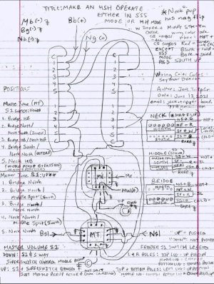
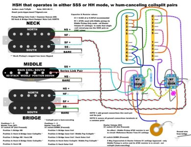
1. Middle Pickup active by itself (traditonal Position 3 on a Strat) is not a position on the 5 way Superswitch in this scheme, but instead, you get that option by using a Fender S1 switch to override the 5 way superswitch. I have the Master Volume pot setup with this S1 switch/pot.

2. The scheme currently requires 2 switches, compared to the "just 1 switch" you requested. Particularly, both will need 4 pole type switches So I have set the Master Tone pot up as the 2nd Fender S1 switch/pot.

I've attached the sketch to this thread, and since some forum members have told me that a diagram attached to a thread gets blurry when zoomed in, following is a link to it at my Imgur account:

https://imgur.com/gallery/V6C7yg3


With the Master Tone S1 switch not pushed (labeled as "Down" in my diagram), you have the HH configuration you requested. Both Inners and Both Outers in Positions 2 and 4 are hum-canceling.

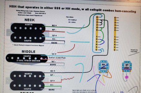
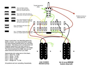
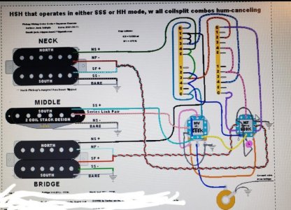
With the Master Tone S1 switch pushed (labeled as "Up" in my diagram), you have the SSS configuration. Because the choice of which coils of the Neck and Bridge humbuckers to split in SSS mode are driven by the magnetic polarity of the Middle pickup, and you had said you wanted to use the STK4m pup whose Main coil has a South Up magnetic polarity, the two active splitcoils of the Bridge and Neck humbuckers in SSS mode are therefore the North coils. This plus the STK4M being coilsplit when the Master Volume S1 is NOT in Override mode gets you humcanceling in Positions 2 and 4. Which means Position 3 featuring Neck and Bridge North coilsplits combined is not hum-canceling. However, this is a case where you could just not even use Position 3 in SSS mode and instead just use the Master Volume S1 switch to get you Middle Pickup only (which IS hum-canceling because I set it up to be the full stack/in series in this override mode). You still have the option to use Position 3 if the venue/room you're playing in doesn't have a lot of RF noise. If you're open to one additional 2PDT switch being added to the scheme, we could use it to split one of the two humbuckers to the South coil in Position 3 temporarily to get hum-canceling in Position 3 in SSS mode.

In order to make the Neck humbucker's North coil also be the outer coil of that pickup in SSS mode (and to also have Inners and Outers in Humbucker mode be hum-canceling), I designated the Neck humbucker to have a mag flip. Which reverses the electrical polarities of the 4 conductor wires, and that is why you see Neck humbucker's Green wire being used as the Hot wire instead of Black wire.

If you were to use a neck or bridge SD Stack pickup in the middle position instead of the STK4m, those have North Up magnetic polarities, so the scheme would have to be modded so that the Humbuckers get split to the South coils instead.

And, the scheme can be tweaked so the S1 switch functionalities switch places btw the 2 pots.

Not all the ground wires are drawn, like the ones that connect the pots to the jacks, or the bridge ground wire. Also not present is a 470K resistor to use eith the Middle pickup, to knock down the brightness since the pots are 500K values.

If the caveats are ok with you, then i would be glad to spend more time and create this in some circuit design software that is in color with the correct pickup wiring code colors, cleaner wiring lines, and overall better layout.

Let me know!
 

Attachments

  • photo102351.jpg
    photo102351.jpg
    103.5 KB · Views: 0
Last edited:
If the middle was always split, then it may as well just be an SSL-1 or SSL-1 RWRP, right?

Darkside,

Just to clarify about tbe last diagram posted in Reply #26, it solves all the concerns I mentioned a few replies earlier, like possibly needing a 3rd switch or the middle pickup having to be left set at coilsplit mode permanently. This last diagram accomplishes everything in your original request with just 2 Fender S1 switches.

I've also decided to go ahead and create a more cleanly laid out electronic version of this in color using a circuit design app. I will post that here when done sometime in the next couple days.
 
Status update: Circuit design software version of the diagram is in progress. Unfortunately its not a quick process, at least in this software (DIY Layout Creator). But then again, it cost me nothing, being freeware, so there is that...
 

Attachments

  • photo102333.jpg
    photo102333.jpg
    90.2 KB · Views: 0
That actually looks really good!

Thanks!

One reason it is a slow process is that this software does not have a line shape available like in Visio, where it stays continuous as you drag it and make various up and down 90 degree turns. Instead, the closest line shape is one where you can get only 1 hard turn at most. And you cannot get 90 degree angles either in just one click, you have to spend time finessing a soft curve to emulate a 90 degree turn. So for example, look at the Black lead wire from the Bridge pickup and how it needs 4 hard turns. That is only possible by combining multiple black lines together. And the other reason this takes time, is that you cannot get the two ends of the lines being joined to snap together seemlessly on first pass. You have to drop one end in place not joined, and then take incremental actions of "nudging" it up or down by increments of 0.02" until the two ends meet. It's a pain. Lol
 
Last edited:
The 2 poles of the push-pull are already fully consumed with the task of A) deactivating the Middle coil (Pole 1) and allowing the signal to pass to the Master Volume from the humbuckers instead of the Middle Pickup in Position 3 (pole 2). So the choices for which coils to split to, cannot be placed into a push-pull cuz it only has 2 poles. Instead those decisions must reside in the superswitch. And the superswitch can only be set up w the coilsplit plans for Mode 1 (HH) or Mode 2 (SSS).

If you use an S1 switch instead of a push-pull, you get the additional pole needed to override one of the the coilsplit choices in the superswitch, and without having any additional physical maneuvers required. It's still just 1 motion (push), like the push-pull pot. And actually, a push motion is more ergonomic than a pull motion.

Darkside,

Was that diagram you posted above created in a software designed for creating guitar wiring diagrams? If yes, could you tell me the name of it, and what the ballpark cost was if it is not freeware?

Thanks
 
Give me a little time to review all your posts.

I used Visio, I have it on my work laptop. It’s not the best tool for electrical schematics, although I’ve used it in the past for that purpose!
 
This is not exactly your request, but it is similar if it helps.
 

Attachments

  • Rick's Wacky Wiring, jpeg updated.jpg
    Rick's Wacky Wiring, jpeg updated.jpg
    107.1 KB · Views: 0
Darkside,

Sure, no problem.

FYI: i've got family business to attend to for the next few days, so I probably won't be able to resume development on the software version of the diagram until Sunday at the earliest.
 
Last edited:
Spotted an error in the pencil-and-paper diagram, involving the routing of wires btw the top and bottom poles of the MV S1 switch. Fixed. Reply # 26 updated with revised diagram attached plus link to the diagram at my Imgur account updated.
 
Last edited:
Give me a little time to review all your posts.

I used Visio, I have it on my work laptop. It’s not the best tool for electrical schematics, although I’ve used it in the past for that purpose!

Darkside,

I've completed the version created in circuit layout software (DIY Layout Creator). Attached is a pic of it.

In case the forum software doesn't hold good resolution when you zoom in on the attachment, following is a link to my Imgur account where you can download a hi-res version of the diagram.

https://imgur.com/gallery/P2lLeCk

Let me know if you have any questions.
 

Attachments

  • photo102486.jpg
    photo102486.jpg
    116.9 KB · Views: 0
Last edited:
Darkside,

I've completed the version created in circuit layout software (DIY Layout Creator). Attached is a pic of it.

In case the forum software doesn't hold good resolution when you zoom in on the attachment, following is a link to my Imgur account where you can download a hi-res version of the diagram.

https://imgur.com/gallery/YD0ijVR

Let me know if you have any questions.

Holy Batman!!!
 
Wow, absolutely fantastic! Thank you for this!

Cool, glad you appreciate it.

This is one of the few ideas for a custom scheme I've seen that, while yielding a ton of tonal options, also remains uber simple in how to engage snd switch btw those options in a live performance setting. So thank you for dreaming up the idea.

Being practical in its operation, it has big potential for adoption by alot of HSH players. I really hope that happens.

Please post back here about your impressions of it once you get it wired up!
 
Back
Top