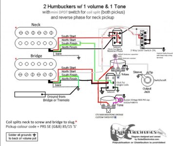
The wiring diagram I recently posted with the PRS wiring color code, i would only trust for the wiring color codes. But not trust for how it shows connections btw the wires being made. For example, it has a goofball error on how the bridge pickup is connected. It has the North Finish (black) and south start (red) wires being joined together. That would only make sense if South Finish (green) was being used as the Hot wire for the pup (this is an alternate connection method that I have not explained yet), but its being used as the ground. So the bridge pickup is wired so that the South coil is out of phase with the North coil. Yuck. And it has the Neck pickup wired out of phase as the default. That's weird. Usually you wire a pup to be In Phase by default, and flip it out of phase with a switch. Here, you need to use the switch just to get it from out of phase to in-phase.
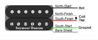
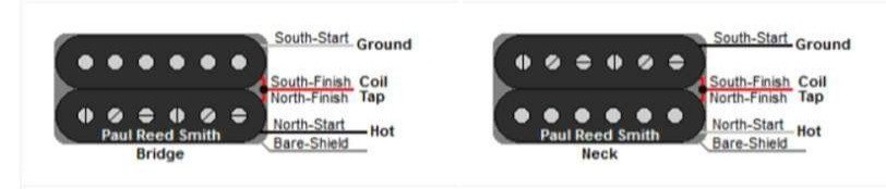
Anyways, if we can at least trust the wiring color code in this diagram (fingers crossed), we are being told that for PRS 85/15S pickups, when compared to how a duncan humbucker is normally wired in series, White wire is the Hot wire (North Start), black & green are joined together for the series link pair (the 2 finish wires) and Red (south start) is the cold/ground wire.
On that basis, to get Both Outer Coils for splitcoil mode on your tonepot push-pull, you would route both Bridge and Neck pups' black/green wire pairs to ground, and for Both Inner Coils, route Bridge black/green wire pair to where Bridge hot wire connects to the 3 way blade switch, and Neck black/green wire pair to where Neck hot wire attaches to the 3 way blade switch.
")