Does this master series-parallel wiring diagram seem valid?

Re: Does this master series-parallel wiring diagram seem valid?

So one thing minimally you will want to change, is to separate the shield/screen from the "cold/-" of the pickup. The shield/screen will still get grounded, but just separate from the pickup's "cold/-". This is done to prevent the EMI/RFI noise present in the signal of the "shield/ground" from getting fed into the output signal when that pickup's "cold/-" is daisy chained In Series with the other pickup. That would add unnecessary noise to your output signal.

Jack, I'm trying to take this into account while thinking about my diagram, but I can't quite get my head round this issue. You gave me this feedback in response to my diagram that attempted to integrate the 1728.com diagram with my 335 wiring. What I can't understand is how I ground both the shield and the pickup's cold/- without them being grounded together, because isn't the ground connection continuous? It sounds like you're suggesting that for example I take the shield to the back of a pot, and then the pickup's cold to the back of another pot. But when those pots get grounded together, won't this have the same effect as grounding the shield and the cold together, as they'll still be in contact with each other, via the grounded pots?
I hope I explained this clearly enough, it's tricky to describe. If you want me to elaborate I would do a quick drawing of the connections. Thanks for your advice.
 
Re: Does this master series-parallel wiring diagram seem valid?

Jack, I'm trying to take this into account while thinking about my diagram, but I can't quite get my head round this issue. You gave me this feedback in response to my diagram that attempted to integrate the 1728.com diagram with my 335 wiring. What I can't understand is how I ground both the shield and the pickup's cold/- without them being grounded together, because isn't the ground connection continuous? It sounds like you're suggesting that for example I take the shield to the back of a pot, and then the pickup's cold to the back of another pot. But when those pots get grounded together, won't this have the same effect as grounding the shield and the cold together, as they'll still be in contact with each other, via the grounded pots?
I hope I explained this clearly enough, it's tricky to describe. If you want me to elaborate I would do a quick drawing of the connections. Thanks for your advice.

Hey Den,

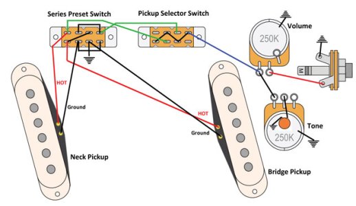
At that time I did not spot in your diagram that you had already accounted for my concern, by routing the neck pickup's earth wire to ground separate from the neck pickup's ground wire. So you are already set with this issue.

What the concern is about those 2 wires in Master Series-Parallel (MSP) switches, is that if you routed the two wires to the same spot (i.e. the middle right lug of the MSP), then in Series mode, then the baseplate and cover of the pickup would get connected to Hot signal and instead of the EMI/RFI that these sources pickup being eliminated by getting sent to ground, they would be amplified and made to be an even worse problem than just being ungrounded.
 
Re: Does this master series-parallel wiring diagram seem valid?

Thanks for getting back to me Jack. I did separate the shield and the cold for the neck pickup, because the 1728 diagram calls for the cold to go to that lug on the switch, but it obviously doesn't account for a pickup with a separate shield, which I know needs earthing. However, I do have the shield and the cold wired to the same lug for the bridge pickup. Because the 1728 diagram says to ground the pickup's cold - and I know the shield needs to be grounded too - so I wired them both to the ground lug on the bridge volume pot. It's probably hard to interpret on my diagram because I drew the bridge pup's cold and shield wires as one wire theoretically twisted together, but if you follow the wires from the bridge pickup you can see that the one that goes to that lug on the vol pot is marked with both a "-" and an "E" (for Earth, representing the shield wire), which is there to tell me to take both wires there.*
Are you saying that it doesn't matter because I did it right with the neck pickup, or is it still a problem? Like I said, I don't really see how I could separate those two wires from contacting each other, when they both go to ground.

*If you don't remember, that diagram I posted was only drawn as a reference for me when I came to wire the guitar, so when I drew it I wasn't worried about making it really clear to anyone else, because I didn't think anyone else would see it haha. So that's why it's not too easy to read unfortunately, sorry.

Your diagram in Reply #18 is all set as-is with regards to this topic of separating ground and earth wires. The bridge pickup's earth and ground wires are not part of the MSP switch, so they don't need to be separated. But the neck pickup's two wires need to be separated (which you have already done in your diagram) because it is part of the MSP switch, and my prior reply provides some detail why its necessary.
 
Last edited:
Re: Does this master series-parallel wiring diagram seem valid?

Your diagram in Reply #18 is all set as-is with regards to this topic of separating ground and earth wires.

Got it, thanks Jack. Okay I get the distinction between the neck and bridge pickup now - because one pickup's cold goes to the switch. Thanks for clarifying that for me, I've got the pickups now so in the meantime I've decided to wire them in with just a master vol and tone, but I remembered you said something about separating the cold and shield so I wanted to make sure I was doing everything right before going ahead with the work.
Thanks again.
 
Re: Does this master series-parallel wiring diagram seem valid?

Great ! Good luck with the upcoming soldering job. Let us know how it goes and what you think of the new In Series mode.
 
Re: Does this master series-parallel wiring diagram seem valid?

Good luck with the upcoming soldering job. Let us know how it goes and what you think of the new In Series mode.

Thanks man! I'm wiring it up as we speak, I'm actually kinda grateful to only be working with two pots at this point haha
 
Re: Does this master series-parallel wiring diagram seem valid?

Well, I got it all in the guitar last week with two pots (and two dummy pots) and it works great! It was my first time working on electronics for a hollow body, and I didn't enjoy that. Yesterday I switched my Mustang to this wiring which changes one of the stock switches to serve the same function as the push/pull in my 335 and I love that too. Gotta say I love Fenders for how you can just wire up a pickguard and then drop it in. Working on that was a dream.

Aug16_PG_CLM_Mod-Garage_WEB.jpg
 
Re: Does this master series-parallel wiring diagram seem valid?

Well, I got it all in the guitar last week with two pots (and two dummy pots) and it works great! It was my first time working on electronics for a hollow body, and I didn't enjoy that. Yesterday I switched my Mustang to this wiring which changes one of the stock switches to serve the same function as the push/pull in my 335 and I love that too. Gotta say I love Fenders for how you can just wire up a pickguard and then drop it in. Working on that was a dream.

View attachment 105771

Congrats!

One alternative method for non-pickguard based guitars that makes wiring them at least a little easier, is to create a cardboard template of the control cavity and where its components sit within, then remove all the components, poke them through the template to hold them in place, and do your connections soldering there on the template outside the guitar.

If you feel making a template is too much work, you could still minimally remove components from the guitar to wire each one, then re-install it. I always do that at a minimum. I feel too cramped trying to reach into the cavity and touch the right spot on an installed item with a soldering iron.
35f359d8cc67e5390b831638c90a4af0.jpg


Sent from my SM-G960U using Tapatalk
 
Re: Does this master series-parallel wiring diagram seem valid?

create a cardboard template of the control cavity and where its components sit within

I did create a template on a serial box, which provided a nice stable base as the underside was flat against the surface of the desk. It was more getting the wiring loom in the guitar that was a bit of a pain��I did the thing where you run string through each pot hole and then tie the end round the pot shaft and pull the components into place, but the hard part was actually tightening all the nuts on the pots and jack without being able to properly grip the other side of the components. Anyway I'm sure I could find some good tips online for that sort of thing.
 
Re: Does this master series-parallel wiring diagram seem valid?

I did create a template on a serial box, which provided a nice stable base as the underside was flat against the surface of the desk. It was more getting the wiring loom in the guitar that was a bit of a pain��I did the thing where you run string through each pot hole and then tie the end round the pot shaft and pull the components into place, but the hard part was actually tightening all the nuts on the pots and jack without being able to properly grip the other side of the components. Anyway I'm sure I could find some good tips online for that sort of thing.

Ah, good.

I re-read your reply from yesterday and see that i missed you saying the guitar was a hollow-body. I have heard those are tougher to work on.
 
Back
Top