Double neck wiring question

With that being said, I will share some info I picked up in a different forum today. This might explain things.

This is because of the common ground?
No, It happens because of capacitively-coupled crosstalk between the two output wires inside the cable due to the very high-impedance environment.

Why then didn't they do this when the two sets of wires I used to have, hit the common ground of my gear?
Because they were physically separate wires, so the capacitive coupling was negligible. The common ground is completely irrelevant.

So I'm correct in assuming that this passive arrangement is not going to work as is?
Only if you use separate cables.

Using a cable with two individually screened cores would undoubtedly help, but I expect you'll either need physically separate outputs and two separate cables (as per your trial rig), or active buffering circuitry inside the guitar to convert from the high-impedance internal wiring to provide low impedance outputs.

Ironically, I was about to evoke capacitive coupling as a possible explanation among others and have renounced to post about that because capacitance is something that I mention way too often in my posts. :-P

Now, what you quote appears to me as logical and clear at first glance. Not that you need to know my feeling about that but it doesn't harm either. ;-)

Hope you'll find a solution.
 
That's interesting. I've done stereo guitar wiring and used a TRS cable from my guitar and split it at the amps and haven't experienced cross-talk like that. I'm surprised.
 
If it's a question of capacitive coupling, it's necessarily random and guitar dependent: wrap a dual conductor on itself or simply press it and its stray capacitance will increase... A pot or jack plug has also its intrisic parasitic capacitance, like any component with hot and ground in the chain. Among physical properties, it's one of the most difficult to predict and to really master when it comes to guitar pickups and wiring IMHO.
It's even tricky to evaluate since basic DMM often add the capacitance of their own probes to a measurement (!).

Ironically, a piezo can be modelized as a capacitive captor, BTW.
 
Just to follow up on my findings. I have still been working on a solution to this. I successfully blocked the piezo from coming in to the magnetic side with a small 9 v circuit I made, however I was noticing a drop in signal level overall just as you would in the middle position of a three way switch with two pickups. I was having every kind of issue as long as I was using a stereo cable. Then I recalled I had a stereo in to two mono outs adapter Y. Plugged that into the stereo jack on the guitar and two separate cables out to my stuff and it works 100% as it should. No buffers.

So I identified the culprit. The stereo cable is the problem.

Does anyone think I would have any luck making my own wrapped screened 2 core shielded version?

How does a Blackout preamp work? I can't find any real literature on how to wire it and if it has two discreet preamps. Maybe that could work?
 
So I identified the culprit. The stereo cable is the problem.

Does anyone think I would have any luck making my own wrapped screened 2 core shielded version?

Being busy, I realize that I've not followed this topic attentively enough and didn't visualize exactly what was the signal path involved... but I hope I get it now. :-P

Regarding your question, there's the beginning of an answer in my previous answer.

I have to ask what is the stereo cable that you use: brand? Lenght?

Anyway:

-any physical proximity between insulated wires will create a stray capacitance increasing with lenght. For guitar cables, see this chart: https://www.shootoutguitarcables.com...nce-chart.html
...and consider that I've personally measured up to 300pF per meter on some cables not mentioned in this shoot out;

-unless a pristine clean tone is desired, cable capacitance is not detrimental for passive magnetic pickups: the higher it is, the warmer is the sound because of a low pass effect. the first section of this page gives an explanation is needed: http://zerocapcable.com/wordpress/?page_id=209

-cable capacitance is detrimental for a piezo pickup wired passively. That's one of the reasons why piezo's are generally associated with onboard preamps;

-so, I'd still use two different cables with different specs next to each other for a dual passive path : a normal guitar cable for the magnetic side and something like Sommer LLX for the piezo (Sommer Spirit LLX being the lowest capacitance coax guitar cable on the market albeit not too expensive IME, at least not until a recent past and here in Europe).

For the record, my uber modified Variax has two output jacks feeding two separate 5m / 16,5ft cables, wrapped together each meter only. I've used this cumbersome assembly on stage for years without issues...

EDIT - Have just measured the stray capacitance values exhibited by a 15ft Planet Waves TRS cable:
Tip to ground: 504pF
Ring to ground: 492pF
Tip to ring: 278 pF. it's twice less than capacitance from each "hot" to ground but still not negligible (the treble pot control of a typical Fender amp is based on a 250pF cap, for the record. In series and not to ground but you get the picture). Probably enough to generate audible capacitive coupling.
 
Last edited:
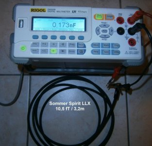
As a footnote and to compare with the values of the TRS cable in my last post , below is the capacitance measured on 3,2m / 10.5ft of Sommer Spirit LLX. The lab meter used has a compensation setting nullifying the cap of the probes.

173pF divided by 3,2 = 54pF per meter. It's a wee bit more than the 52pF mentioned in the shoot out of my link above, because of the inner capacitance of the jack plugs used (less than 7pF for both in this case).

That's what I'd use for a passive piezo. YMMV.

SommerSpiritLLXrd.jpg
 
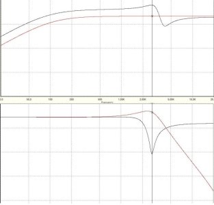
Footnote bis - Out of curiosity, I've botched a crude 5spice model of piezo & mag humbucker with and without capacitive coupling between tip and ring of a TRS cable. Upper part of the pic = piezo + its volume with and without coupling. Lower part of the pic = magnetic passive transducer (DD specs & with 500k volume + tone) with and without coupling too. Red line = pure signal of each pickup alone. Black line = altered (bleeding) signal of each pickup, even when the other is disabled.
Overall cable capacitance simulation was moderate in this case: 320 pF from hot to ground (= typical of a 10ft cable). Higher than this, it would have altered the pure signal of the piezo in a more noticeable way.

Don't know if this pic is accurate or not but it makes sense to me (and if ever it's not wrong: as mentioned by beaubrummels, it would involve some kind of AC stray signal; but passing through capacitive coupling between "hot" wires rather than through ground).

I've also edited my statements above in order to exorcize any seducing but misleading forced antithesis lacking of nuance... < ; 0 x

FWIW (I've fun with strange things, I know).

Piezo&MagCapCoupling.jpg
 
Thank you for going through all that. I get the feeling you enjoyed this. I wish I knew more about everything that you say but I don't not understand it in some small way either. I never in a million years would have thought something like this could even happen.

It seems an analogy might be something like this:

Two highways right along side each other, separated by a barrier. Two people just walking down each can easily jump over to the other side without much ado. Those same two people racing down those same streets at breakneck speed would not be able to jump the median without a catastrophe therefor they continue on the established route.

I'm not wanting to complicate this too much and I think the Fishman powerchip will solve all these issues in the most efficient way. I even asked Brian Moore what his solution was. Outside of the preamps his guitar use he suggested the Fishman, which it just so happens I won an auction for a used one one eBay this very moment for 26 bucks. Not bad seeing as they're 130 new.
 
Just as a follow up. I installed the Fishman Powerchip and although it does offer the switching I sought, It is not 100% isolation. Essentially it is an acoustic preamp linked with a way to switch and control things along with the electric side. The result is total isolation of the acoustic from the electric but not so much the other way around. The acoustic can punch through the electric. Maybe this is not such a big deal if you have both styles of pickup on ONE guitar but I have a doubleneck. I assume even a simple buffer pre on the electric would solve the whole thing I have not gotten there yet. Even Fishman says the electric side is untouched meaning there is no buffer there. Battery life is impressive though.
 
Back
Top