You are using an out of date browser. It may not display this or other websites correctly.
You should upgrade or use an alternative browser.
You should upgrade or use an alternative browser.
Followed Stewmac diagram... no sound...
- Thread starter Jermo3178
- Start date
SGFanatic
New member
Re: Followed Stewmac diagram... no sound...
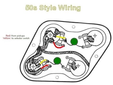
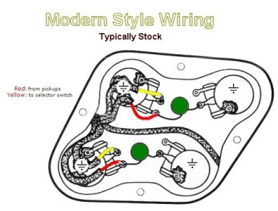
Here are 2 wiring diagrams


The braided wire in the pic is the ground. You just solder the ground wires on your pickups to the back of the pot and you'll be good.
And I might be crazy, but I don't see wires from the output jack in the photo either.
It's wrong, but you could unsolder everything very carefully and start over. Just be careful when your unsoldering the caps. Just hold the wire to the cap with some needlenose as a heat sync. I like to make a template of the configuration on a piece of cardboard and work outside of the electronics cavity. It's a lot less stressful and safer. Just remove all the pots and trace the hole placement through the back of the guitar onto cardboard. I always use the USPS box my stuff came in. Poke holes in the cardboard and stick the shafts of the pots through. Now you can work on the pots without chasing them all over your work area with your iron.I apologize for the sporadic beginning of this tread... The frustration, need to be in bed about 3 hours before I figured out something was wrong, and let's not forget to take into account my NOOB (forum and guitar modding) status kicked in.... and it speaks volumes.
View attachment 49674
Here is a pic of the diagram
View attachment 49675
Here's what I have, minus the 3way switch
Here are 2 wiring diagrams


The braided wire in the pic is the ground. You just solder the ground wires on your pickups to the back of the pot and you'll be good.
And I might be crazy, but I don't see wires from the output jack in the photo either.
Jermo3178
Member
Re: Followed Stewmac diagram... no sound...
Quick question before I get started again.. would this diagram be better or the SD diagram?It's wrong, but you could unsolder everything very carefully and start over. Just be careful when your unsoldering the caps. Just hold the wire to the cap with some needlenose as a heat sync. I like to make a template of the configuration on a piece of cardboard and work outside of the electronics cavity. It's a lot less stressful and safer. Just remove all the pots and trace the hole placement through the back of the guitar onto cardboard. I always use the USPS box my stuff came in. Poke holes in the cardboard and stick the shafts of the pots through. Now you can work on the pots without chasing them all over your work area with your iron.
Here are 2 wiring diagrams
View attachment 49747View attachment 49748
The braided wire in the pic is the ground. You just solder the ground wires on your pickups to the back of the pot and you'll be good.
And I might be crazy, but I don't see wires from the output jack in the photo either.
SGFanatic
New member
Re: Followed Stewmac diagram... no sound...
I think this is even easier, but you could reference both. This one has the tone caps from volume pot to tone pot, the SD has them on the pot themselves. I'm not sure there is a difference. I've used this and I like it.Quick question before I get started again.. would this diagram be better or the SD diagram?
KnifeR
New member
Re: Followed Stewmac diagram... no sound...
Connect the ground of jag output or 3 way toggle to the ground of pickups or pot housing!! - there is no circuit connections!!!!!!
dont connect the input (middle of 3 way toggle) with housing of pots!!! - this will make no sound!!!
I apologize for the sporadic beginning of this tread... The frustration, need to be in bed about 3 hours before I figured out something was wrong, and let's not forget to take into account my NOOB (forum and guitar modding) status kicked in.... and it speaks volumes.
View attachment 49674
Here is a pic of the diagram
View attachment 49675
Here's what I have, minus the 3way switch
Connect the ground of jag output or 3 way toggle to the ground of pickups or pot housing!! - there is no circuit connections!!!!!!
dont connect the input (middle of 3 way toggle) with housing of pots!!! - this will make no sound!!!
Last edited:
Jermo3178
Member
Re: Followed Stewmac diagram... no sound...
Been a crazy week, so I couldnt get to it.. bout to hit it this weekend. Wondering one more thing... Does this give the independent volumes? or the shared volume?
I think this is even easier, but you could reference both. This one has the tone caps from volume pot to tone pot, the SD has them on the pot themselves. I'm not sure there is a difference. I've used this and I like it.
Been a crazy week, so I couldnt get to it.. bout to hit it this weekend. Wondering one more thing... Does this give the independent volumes? or the shared volume?
SGFanatic
New member
Re: Followed Stewmac diagram... no sound...
This will give you independent volumes, and of course with the switch in the middle position you can bleed all the pots together, if you choose.Been a crazy week, so I couldnt get to it.. bout to hit it this weekend. Wondering one more thing... Does this give the independent volumes? or the shared volume?
Jermo3178
Member
Re: Followed Stewmac diagram... no sound...
I did, but I took that out when I made the pic. After redoing everything the second time, I ended up with 4 volumes... 3rd times a charm...
it would appear you didn't solder the middle lugs of the volume pots to the toggle and the toggle isn't connected to the jack. check that out. the schematic of stewmac is just fine.
I did, but I took that out when I made the pic. After redoing everything the second time, I ended up with 4 volumes... 3rd times a charm...
Jermo3178
Member
Re: Followed Stewmac diagram... no sound...
3rd times a charm!!! We have success... And it sounds B*TCH*N!
I want to thank everybody for the great advice, words of encouragement, insight... and the smacks on the back of the head. Truthfully though, Thanks for everything!
Now off to get another JB/Jazz set, to go back to work on the Tele...
3rd times a charm!!! We have success... And it sounds B*TCH*N!
I want to thank everybody for the great advice, words of encouragement, insight... and the smacks on the back of the head. Truthfully though, Thanks for everything!
Now off to get another JB/Jazz set, to go back to work on the Tele...
Last edited:
chadd
New member
Re: Followed Stewmac diagram... no sound...
The most important thing is to take your time and verify every connection you are about to make. It may seem tedious at first, but it can save a lot of duplication of effort and troubleshooting on the back side.3rd times a charm!!! We have success... And it sounds B*TCH*N!
I want to thank everybody for the great advice, words of encouragement, insight... and the smacks on the back of the head. Truthfully though, Thanks for everything!
Now off to get another JB/Jazz set, to go back to work on the Tele...
Jermo3178
Member
Re: Followed Stewmac diagram... no sound...
Oh yeah, definitely... I ended up replacing the harness I bought with different CTS pots, Switchcraft jack and switch, and the caps... rewired everything from scratch.
I'm gonna clean the Stewmac harness up and use those parts elsewhere. My son thinks he wants an LP, and my lead guitarist has one too.. 2 prime candidates right there...lol.
I have to say since doing all this, and finally having something... I like this modding thing better than I had thought.
Last edited:
F
Funkfingers
Guest
Re: Followed Stewmac diagram... no sound...
Psst. Wanna buy some magnets? :deal: The first one is free, maaaaan. :naughty:
Psst. Wanna buy some magnets? :deal: The first one is free, maaaaan. :naughty:
