Ground Loops in guitar wiring - fact or myth?

CarlosG

New member
Hi!
I wonder if ground loops are actually possible in wiring.
There is a ton of material on the internet both for and against.
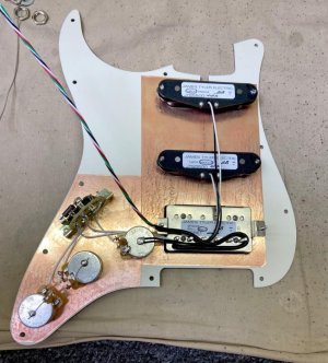
It seems stupid, because looking at the loaded pickguard seymour duncan, dimarzio, fende, they make ground loops.
The potentiometers get ground through the shielding, and are connected by cables.
I've noticed that I really like the sound of Suhr and James Tyler guitars, I think they're top-shelf to my ears.
I analyzed the pictures of the pickguards and electronics and it turned out that both avoid ground loops. The potentiometers have grounds given only through the shield.
I wonder if this is a factor that has a positive impact on the sound.
I don't think they're saving on a piece of cable. It seems they're not connecting the potentiometer housing with justification.
James Tyler pickguard (no ground wire/ no ground loops)

Suhr (no ground loops)
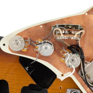
used-suhr-classic-antique-hss-sunburst-2014__90878.jpg


James Tyler (no ground loops)
86698397_2855297214516409_5854342171670347776_n.jpg
 
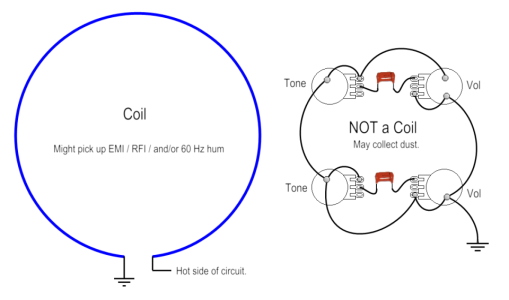
Myth! There isn't enough energy within (passive) guitar wiring to create a ground loop. I suppose it might be possible with active pickups, but I strongly doubt it.

Coil.png
 
With guitars, there's always one common path to ground - the guitar cable. If your shielding tape is properly connected to this ground there's going to be no measurable resistance between it and ground, so ground loops are not a real issue. If you surround your control cavity with shielding tape and then ground it, you effectively create a Faraday cage . . . which is very protective against electrical noise/interference.
 
In the house, all grounds are brought to one point, and yet the ground loop phenomenon occurs. As I mentioned earlier, I don't think Suhr and Tyler are saving money on a piece of cable.
 
It's impossible to have a "ground loop" within a guitar because there is only one ground source at the jack. Whether you ground through the shield or explicitly wire the pots together, it has the same effect and doesn't change the sound. It just saves a bit of time in assembly and lowers the risk of damaging a pot by too much soldering to the housing, though it looks like they are still wiring stuff to the back of the pots. (I've actually done guitars where I didn't solder any of the backs of the pots at all; I ran all the grounds to a common washer and out to the jack.

A house is divided into different circuits and you can get two different ground sources referencing against each other creating a "ground loop". If you had a stereo guitar with two jacks and each jack went to two different amps that were plugged into two different circuits, maybe I could see that happening, maybe.
 
I can see where a loop might cause an antennae
but in guitar wiring it would be a very small one
and inside a shielded control cavity
probably not an effective one
 
One of the easiest examples of a ground loop to understand, is when people started installing high power car stereos. Head unit in the dash, high power amp in the trunk. A car chassis isn't that pure of a ground. Ok for taillights, not so much for high quality audio. Since a high power amp in the trunk can draw stupid amps, you'd have a potential difference between the amp ground, and head unit ground. Add to that, the ground made through the RCA connectors, and a ground loop is born.

You just don't have that within the confines of a guitar control cavity.

Think of any old vintage Pioneer, Sansui, Sony, Kenwood, stereo et al. High power, and how many ground points within the chassis. But no ground loops, hum or buzz.
 
Myth.

No way you can build up enough resistance inside a guitar to have different potentials.
 
It only takes a few mV of potential difference to have an audible noise at the input of a guitar amp. It could be a risk if you are careless about where you ground the volume control and pickups. Grounding at a single star-point minimises the potential differences.
 
It only takes a few mV of potential difference to have an audible noise at the input of a guitar amp.

But that's the thing. There won't be any potential difference. Using my car stereo example, both the head unit and the amp, are powered devices, separated by say, 6 - 8 feet. In a guitar, the pickup is a tiny AC generator. The pots aren't powered, therefore there can't be any potential difference between them and the pickups. And the full current output of a (passive) guitar is in millionth's of an amp. That level of current, across a few inches of decent wire, won't generate any measurable voltage.
 
The easy way to solve this would be to ask: If there can exist a ground loop in guitar there would have to be two seperate grounding voltages. What are those two voltages?

A ground loop could occur if you had a circuit that grounded to 0v and a circuit grounded to +4.5v and you accidentally attached a ground from the 0v circuit to the ground for the 4.5v circuit. This would cause signal to travel "up" from the ground of one circuit into the other, causing any number of problems.
 
I tested it once and it seemed to me that I couldn't hear any difference between them, but I don't have laboratory conditions, because guitar pickups are sensitive to current interference.
I prefer soldered connections because they are solid, but the topic was interesting to discuss
 
Back
Top