How to wire a 5-way Rotary Switch

JP13

New member
Hey guys,
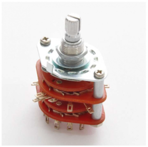
I'm trying to figure out how to wire 1x P90, 1x Hum, 1x Vol., 1x Tone, to a 5-way rotary switch (4 poles)

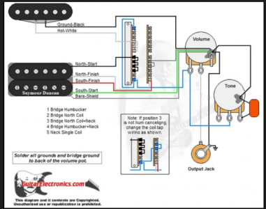
Basically I try to replace the 5-way-super-switch in the wiring diagram with the rotary switch.
To get the said positions:

1 Bridge
2 Bridge North
3 Bridge North + P90
4 Bridge + P90
5 P90

I'm really not into electronics, so I am a little lost here.

And for the love of god, I can't find anything on the internet (looked literally for hours).

Anyone did this before or willing to help me out?

Regards from Germany,
Josh


EDIT:

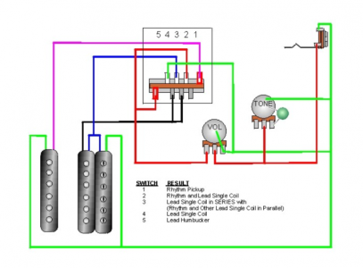
I heard that P90+Hum can be quite much, so here is another (and simpler) wiring diagram, with a regular 5 way-switch. And a new position 3.


sorry for the mess...
 

Attachments

  • 5way.png
    5way.png
    152.6 KB · Views: 0
  • p90 wiring 2.png
    p90 wiring 2.png
    359.7 KB · Views: 0
  • Screenshot 2023-04-08 152546.png
    Screenshot 2023-04-08 152546.png
    243.6 KB · Views: 0
Last edited:
Is that the actual switch you have?
Can you post a pic of the other side? I think I know what it looks like, but more pics is always helpful. Or, the website where you got it.
 
Rotary 5 way switches are wired the same as 5-way super switches, just layed out a little differently. You have the wiring diagram you need, just a little bit of understanding how a super switch works is all you need.
 
Hey guys, thanks for the replies, have been busy.

yes, this is the switch i got, here is the link:
https://www.rockinger.com/parts/elektrik-knoepfe/schalter/958/5-fach-drehschalter

click on "Anschlussbelegung / Pin Assignment"
and you'll see the picture I attached.

ok, since it works like a 5-way super switch, I only need to translate the pins, so to say.
my problem is: I don't know in the wiring diagram I posted which is the A, A1, A2,...

could you tell where the "layers" A, B, C, D are on the 5 way super switch in the wiring diagram from top left to bottom right...?

sorry, I am having a hard time wrapping my head around this, I am really a rookie when it comes to wiring (diagrams)... 5 way.png
 
ok, next problem... how do I know what is A, B, C, D 5 way.png ?
they didn't include an explenation unfortunately...
 
ok, so these are the 5 positions and the pins that get conected in each position... right?
so the pins on the backside/outside get connected to the pickups?
and the two pins in the middle, that get connected to the pins on the outer ring are the ground and the hot...?

sorry man, you don't understand how much of a noob I am... I am really having a hard time with this...
 
I'll do a better diagram a little later today. I'm one of those people that waits 'til the last minute to do taxes.

So . . . coffee>taxes>diagram. :cool:
 
last time I had to pay a fine cause the taxes were overdue...

yeah, a wiring diagram would be awesome! still, I'd like to understand a little more about how the switch works... so I could do it myself...
so is it possible to "translate" a 5-way-super switch to the rotary switch? you know, the A, B, C, D stuff...

I colored the 5 sections of the switch. is it possible to say which of the sections is A, B,..., respectively A0, A1, A2,... or does it work too differently than the rotary switch?

layers.png

and by the way, thanks for the patience and the kindness!
take your time
 
This is preliminary so you can see where the terminals are. Taxes were a bitch. I'll do the diagram tomorrow.

(Transpose the terminals clockwise to counter-clockwise.) Film@11.

switch.png
 
Yep, who doesn't hate taxes...

thanks, yes, I understood the A,B, C, D sections on the rotary switch but I wonder if you can name the sections on the 5-way-super switch A, B C and D.
I colored them in the post before your last post.
another try:

seymour.png

is it possible to say "the section in green represents - for example - section A on the rotary switch", red is B, blue C,..."
and to say for example: "in the green colored section, the first pin on top represents what is called A0 on the rotary switch, the second pin is A1,..." and so on

you know what I mean?
If I could "translate" these 4 sections to the rotary switch, I'd know where to solder everything...
 
The letters are random. So "A" will connect to A1 - A5 and so on. On the superswitch, the four quadrants can be any of those four letters. As long as you stay consistent with its group.
 
I can't edit the above post. Note that where the green "ground" goes, that there's one terminal hidden behind the wafer at the top. Don't accidently use that lug.
 
how unfortunate...

so I guess I'll have to wrap my head around this and get familiar with switches and multimeters...

thanks for the answer though, hope you were successful with your taxes ;)
 
I just noticed . . . the blue line that goes "out to the volume pot" appears to connect to an outside lug. It only connects to the "inner" two.
 
Back
Top