idsnowdog
Imperator of Indignation
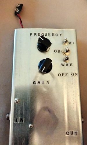
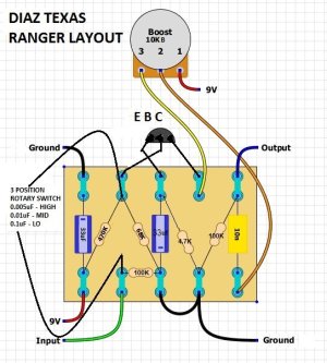
Background: I have been intrigued by the idea of a Treble Booster and cocked wah for years but until recently they were relatively expensive and hard to find vintage/boutique gear. Many of my favorite players used the Dallas Rangemaster so I looked for a schematic and was surprised they are very simple circuits. I found a video on youtube of the Cesar Diaz Texas Ranger and I liked its sound. I also found a layout file and it's very close to a Rangemaster except that it has a three-way switch for low/mid/high capacitor settings.
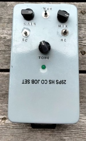
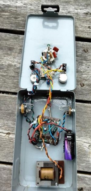
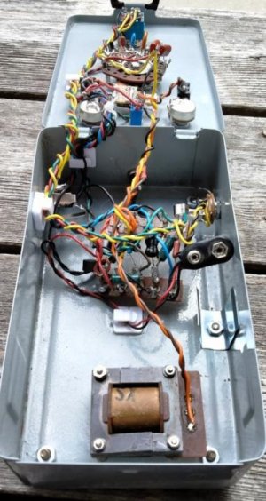
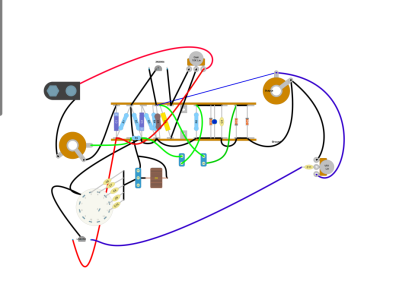
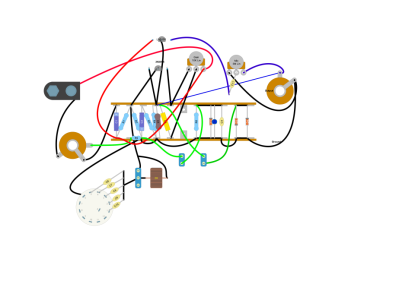
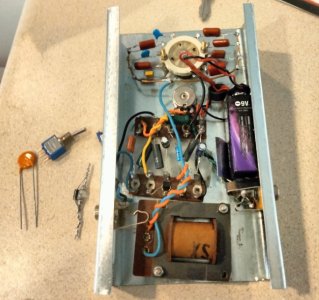
The Build: I started out with 100% recycled carbon comp resistors and tag boards from a 1950s Hammond Organ I scrapped. Although I could have used Germanium transistors I chose 2n3904 Silcon instead. Germanium transistors can be inconsistent, noisy, and sensitive to voltage and temperature changes. While testing on the breadboard I found the circuit was too noisy and had low output. Since there are only six resistors I decided to replace them with 1% tolerance metal films. The change in the noise floor was amazing! It was much louder, cleaner, and less hissy with metal films. Since I didn't have a three-way rotary I used three on/off toggles while testing and I found the three stock capacitor values worked pretty well but could use some tweaking. I found a 1p10t switch at a local salvage place so I wired it up with capacitors ranging in values from: .003, .0047, .0068, .01, .02 , .03, .047, .068, .1. I tried to be "scientific" and separate each of the values by four intermediate values to cover as much ground as possible. However, that experiment was a bit of a bust because there are only five unique values available on the switch. I got three too-dark, one perfect middle, and one too-bright setting. So, I need to go by ear to find five values that work instead of trying to guess which will work based on a chart. I need to find those Michael Schenker and Brian May frequencies. Having experience with Gibson Varitone-style circuits I also chose to install a 3H inductor after the capacitors to affect the Q of the frequency range. I tested with and without the inductor and found the difference was pretty subtle until about the 2/3 point on the volume pot. The louder it gets the more the inductor changes the frequency range. I was going to have the inductor on a switch but I just wired it direct because I like what it does with all settings. The inductor gives the capacitor settings more of a cocked-wah sound.
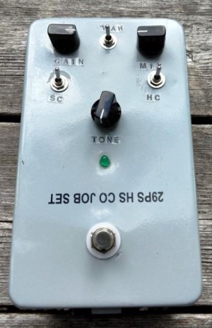
The Evaluation: This thing kicks HARD! It is surprisingly loud and cleans up well by rolling down the guitar's volume. Beyond the 2/3 mark on the pedal's volume, I almost get a fuzz tone. It does Thin Lizzy, Black Sabbath, and Uli John Roth easily. There's something unique about a treble booster that makes every amp sound like it's cranked even at low volume. I also played around with adding simple diode clipping to the output with interesting results. Two Germanium diodes reduce the frequency range and make it sound brighter and more compressed (more warmth but less clarity). Two Silicon diodes make it sound much brighter, tighter, and more aggressive (lots of aggression but no balls). Two LEDs darken and round off the tone (OK for bright settings but otherwise too dark). Two Zenner diodes brighten and compress the sound (weird and hard to explain). Two Schottky diodes brighten, compress, and saturate the sound (juicy with lots of sustain). One Silicon diode is better than two and tightens things up nicely. I might add an on/on switch to choose between two Schottky diodes (smooth) vs one Silicon (tight) option.
The Build: I started out with 100% recycled carbon comp resistors and tag boards from a 1950s Hammond Organ I scrapped. Although I could have used Germanium transistors I chose 2n3904 Silcon instead. Germanium transistors can be inconsistent, noisy, and sensitive to voltage and temperature changes. While testing on the breadboard I found the circuit was too noisy and had low output. Since there are only six resistors I decided to replace them with 1% tolerance metal films. The change in the noise floor was amazing! It was much louder, cleaner, and less hissy with metal films. Since I didn't have a three-way rotary I used three on/off toggles while testing and I found the three stock capacitor values worked pretty well but could use some tweaking. I found a 1p10t switch at a local salvage place so I wired it up with capacitors ranging in values from: .003, .0047, .0068, .01, .02 , .03, .047, .068, .1. I tried to be "scientific" and separate each of the values by four intermediate values to cover as much ground as possible. However, that experiment was a bit of a bust because there are only five unique values available on the switch. I got three too-dark, one perfect middle, and one too-bright setting. So, I need to go by ear to find five values that work instead of trying to guess which will work based on a chart. I need to find those Michael Schenker and Brian May frequencies. Having experience with Gibson Varitone-style circuits I also chose to install a 3H inductor after the capacitors to affect the Q of the frequency range. I tested with and without the inductor and found the difference was pretty subtle until about the 2/3 point on the volume pot. The louder it gets the more the inductor changes the frequency range. I was going to have the inductor on a switch but I just wired it direct because I like what it does with all settings. The inductor gives the capacitor settings more of a cocked-wah sound.
The Evaluation: This thing kicks HARD! It is surprisingly loud and cleans up well by rolling down the guitar's volume. Beyond the 2/3 mark on the pedal's volume, I almost get a fuzz tone. It does Thin Lizzy, Black Sabbath, and Uli John Roth easily. There's something unique about a treble booster that makes every amp sound like it's cranked even at low volume. I also played around with adding simple diode clipping to the output with interesting results. Two Germanium diodes reduce the frequency range and make it sound brighter and more compressed (more warmth but less clarity). Two Silicon diodes make it sound much brighter, tighter, and more aggressive (lots of aggression but no balls). Two LEDs darken and round off the tone (OK for bright settings but otherwise too dark). Two Zenner diodes brighten and compress the sound (weird and hard to explain). Two Schottky diodes brighten, compress, and saturate the sound (juicy with lots of sustain). One Silicon diode is better than two and tightens things up nicely. I might add an on/on switch to choose between two Schottky diodes (smooth) vs one Silicon (tight) option.
Attachments
Last edited: