Is there a problem with this diagram?

Both.
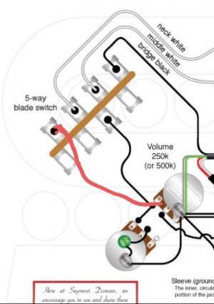
The middle position does indeed allow for a blend....in fact this is exactly the same wiring diagram as found in a Les Paul (save for the fact they have tone controls too). And just like a Les Paul if you drop the volume of 1 pickup all the way down you shut off the whole sound in the middle position.

Hey Alex. That's not quite correct. If the 3-way is in the middle, either volume will kill both pups. The output jack will be shorted to ground through the pot. To get the "blend" affect, (aka 50's wiring), you need to reverse the connection from the left-most terminal to the center. In other words, pickup black wire to the center wiper, and the left-most terminal out to the 3-way switch.
 
50's wiring is not a blend. You're talking independent wiring.
And you can blend the pickups, just only to a certain degree as I mentioned in my post.
 
We may be talking semantics. To me, "independent" is necessary for "blend." When I think of blending, I think of having one volume up, and one down. Then you can slowly bring one up to just the desired amount. You need independent to that.

But I can also see your point that if both are "up", you can bring one down just a bit, before it starts to kill the other pup. So, I guess there is some crossover here.

Edit: I just reread your post. You definitely stated that turning either down will kill both. My bad.
 
Can you explain what is wrong for others visiting this thread?

BeauBrummels is correct, no sound would be produced in either of those.

I added a Red wire that would replace the current, errant Black wire that comes off the volume pot and goes to the 5 way switch.
 

Attachments

  • photo99908.jpg
    photo99908.jpg
    37.2 KB · Views: 0
Coil split to activate the adjustable screw coil. Wiring is incorrect, not sure what the correct way is, but this is not it.
Top drawing is correct, bottom is wrong.
 

Attachments

  • photo100229.jpg
    photo100229.jpg
    50.6 KB · Views: 0
This is the correct way to wire the coil split to activate the screw coil.
 

Attachments

  • photo100230.jpg
    photo100230.jpg
    53.6 KB · Views: 0
Coil split to activate the adjustable screw coil. Wiring is incorrect, not sure what the correct way is, but this is not it.
Top drawing is correct, bottom is wrong.

WDeeGee,

Both are valid methods, just different ways of going about the task. I have used each one successfully in different projects previously. Sometimes because of limitations imposed by the other design elements of the circuit you're working on, you're not able to route the Series Link Pair to Hot like in Method 2 BUT your circuit allows you to route it to Ground, so you employ Method 1 to achieve the end result.

Please see the attached summary "slide" I created in quick-and-dirty fashion, for the 2 methods and the short explanation of each I added to the left. Maybe those explanations will clear something up for you.

Why do you believe Method 1 is incorrect? Did you try it and it not worked? If yes, please start a separate thread and I would be glad to help you troubleshoot it.
 

Attachments

  • photo100232.jpg
    photo100232.jpg
    77.7 KB · Views: 0
Last edited:
And just to clarify, Jack is correct. There's more than one way to "skin a kat", so to speak. Ultimately, what needs to be understood, is that if you want to "kill" the stud coil, you short out black and white. And if you want to "kill" the screw coil, you short out red and green. It doesn't matter, electrically, how you accomplish that. (Talking Seymour Duncan pups here. Others may be different.)
 
I took another look and yes, both methods would work. The second methode keeps the phase the same with both HB on and the first method reverses it?
 
I took another look and yes, both methods would work. The second methode keeps the phase the same with both HB on and the first method reverses it?

No, phase remains normal in both methods.

If you would like to discuss further, please start a new thread. This particular thread is meant to be dedicated to just SD diagrams that have confirmed issues that need to be corrected eventually.
 
Last edited:
in this diagram there is no tone control for the neck pickup. How do we fix that?

This is basically the same question you asked here: https://forum.seymourduncan.com/foru...ot-rail-wiring

Except that bridge and neck are reversed. That's ok. It IS a confusing issue. Normally, the "other" side of the 5-way would be used for tone control assignment duties. But in both of the diagrams that you linked to, that side of the 5-way is used for auto-split. So . . . now you have to decide: 2 tone controls, three pickups. Which gets what? Since in the #2 & #4 positions, pickups share a tone control, you have to pick which pup doesn't get a tone control when used by itself. Or, get a Superswitch.

Personally, I think the whole 2-tone system on a Strat was stupid from day one. Do master volume and master tone, and use the other hole for something far more useable. Like a blend pot.

My 2-cents worth.

Artie,

funny; just finished my analysis and as I am getting ready to respond, you posted just minutes b4 me.

My analysis matches your conclusions and really the only thing I could maybe add is that the diagram being asked about has no actual error -like you explained, the limitations of a 5 way switch that only has 2 poles means you have to give some functionality up if you want to do something different with one of the two poles besides tone control routing - in this case supporting coilsplitting for multiple pickups.
 
My analysis matches your conclusions and really the only thing I could maybe add is that the diagram being asked about has no actual error . . .

Yup. And I probably should have stated that just so as not to confuse the poster, or anyone else, any more than necessary. Good catch.
 
All the forum talk about Blackout's, (specifically, the BMP), made me catch an error in the BMP_Standard_LesPaul diagram. There needs to be a connection between the two red arrows. "Output 2" is the neck output.

BMP_Standard_LesPaul.jpg
 
All the forum talk about Blackout's, (specifically, the BMP), made me catch an error in the BMP_Standard_LesPaul diagram. There needs to be a connection between the two red arrows. "Output 2" is the neck output.


Good catch, Artie.

i see that it also suffers from an incorrect cap value of 0.047uF being listed. As you and I have discussed previously in another thread, Seymour Duncan later revised the wiring instructions sheet that is included with Blackouts preamps to specify a cap value of 0.47uf instead , as smaller cap values led to the tone pot having no audible effect.

Ref:

https://forum.seymourduncan.com/foru...39#post6028139
 

Attachments

  • photo101444.jpg
    photo101444.jpg
    48.5 KB · Views: 0
Last edited:
Back
Top