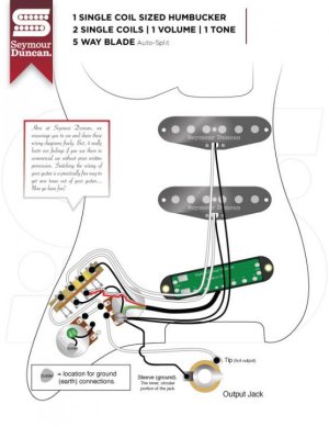
Isn't this wiring schematic from SD wrong?

andersreve

New member
Can someone help me understand this?

If I split the coil on the humbucker using log 6 on the switch, I am grounding the split in both position 1 and 2, because log 6 is on in both those positions.
This will make the humbucker autosplit all the time, right?

And why am I grounding log 7?

What am I missing here?

1SCH_2S_5W_1V_1T_AS.jpg
 
It's not grounding it in position 1, because the bridge/#1 lug is on by itself, and common is open, so it's not doing anything else. It grounds it in position 2 when the bridge is combined with the middle pickup. After that, it does nothing because in position three, the ground is selected by itself and does nothing because there's no common wire on that side of the switch.
 
In my 5 way switch, you dont need to connect lug 4 and 5 - they are always the same - essentially making it a 7 lug 5-way switch.

Doesnt that make it ground the entire guitar in position 2,3 and 4 if I connect lug 7 to ground?

Well I know it does, because thats what's happening :)

In this schematic, is lug 4 and 5 not both common - or are they just common for each side? Because then that ground would make total sense to me!
 
The wiring diagram is correct. The common terminal isn't being used on the "bottom" half of the switch.
 
In my 5 way switch, you dont need to connect lug 4 and 5 - they are always the same - essentially making it a 7 lug 5-way switch.

This doesn't make sense to me. I'd have to see what you are talking about. There are no numbers in the drawing to associate what you are calling lugs 4-5.


Doesnt that make it ground the entire guitar in position 2,3 and 4 if I connect lug 7 to ground?

Well I know it does, because thats what's happening :)

If you have a jumper connecting the two common lugs, you need to remove it from the side of the switch that is doing the split.


In this schematic, is lug 4 and 5 not both common - or are they just common for each side? Because then that ground would make total sense to me!

The common lugs on standard CRL type 5-way blade switches are at opposite ends of the switch. I'm not sure what you are calling lugs 4-5. In the Duncan drawing, the common lug for the pickup selection side of the switch is connected to the volume pot. And the common for the split side of the switch is empty, no connection. That's the only way it would work.
 
Is your switch a box type with all of the lugs in one row? If so, you need to cut the connection between lugs #4 and #5. Those are the "common" lugs and as you can see in the SD diagram with the typical CRL type blade switch, the common lugs are NOT connected in this wiring scheme.
 
Is your switch a box type with all of the lugs in one row? If so, you need to cut the connection between lugs #4 and #5. Those are the "common" lugs and as you can see in the SD diagram with the typical CRL type blade switch, the common lugs are NOT connected in this wiring scheme.

Yes exactly! Thank you.

Cut it? Like, open the printboard?

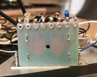
Switch looks like this (I measured, and 4 and 5 are common/always on):
image_109251.jpg
 
Back
Top