Multimeter shows pots resistance instead of pickup resistance when connected to jack

Status
Not open for further replies.

rango

New member
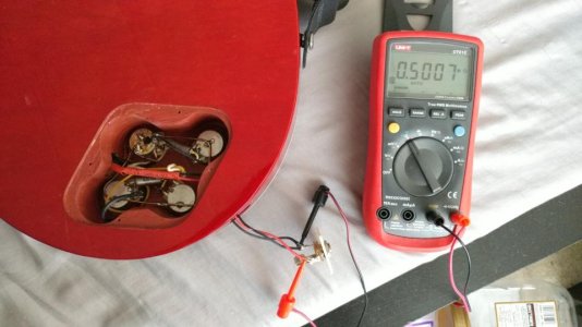
Hi guys. So i rewired my guitar for 50s wiring and i connected guitar cable to output jack and measured it with multi-meter to see if pickups are working.

The multimeter is showing pots resistance of 500k at volume of 10 but it should show pickup resistance instead. When i switch to neck and then bridge pickup it always tops out at 500k which tells me it's measuring pots resistance.

I have measured the pickups resistance before installation and they were working at 8.14k ohm neck and 14.4k ohm bridge so i know they were working before install.

Did i ground pickups or what have i connected wrong that it's not measuring pickups resistance when playing with pots volume?
 
Last edited:
Re: Multimeter shows pots resistance instead of pickup resistance when connected to j

Have you tested with an amp to see what happens when you adjust the switches/controls?
 
Re: Multimeter shows pots resistance instead of pickup resistance when connected to j

I dont have an amp yet. This is my first guitar but i have audio interface for pc. Not much i can check as strings are not on it and i will need luthier to install new nut but i wanted to check if pickups are working as i dont want to add any extra costs in case he finds pickups are not working if i wired something incorrectly.

I know that switch is working as when i switch between neck and bridge the max resistance changes and also when i turn down volume knob the resistance also changes but thats pots resistance of 500k not pickups of 8.14k.

Is it possible that its reading pots as wiring is 50s style not modern?
 
Re: Multimeter shows pots resistance instead of pickup resistance when connected to j

Q: Did you use existing pots?
Q: Looking from the bottom, is the right-most (CCW) lug of the volume pot connected to ground?
Q: Did you use the center lug of volume pot for the output?
Q: Is the CW lug (left-most) of volume pot your input from switch or pickup?
 
Re: Multimeter shows pots resistance instead of pickup resistance when connected to j

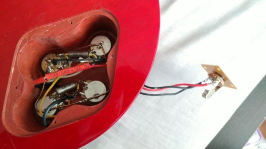
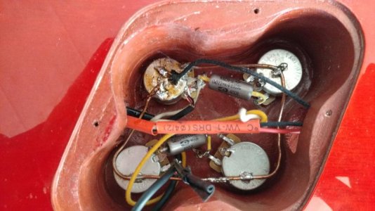
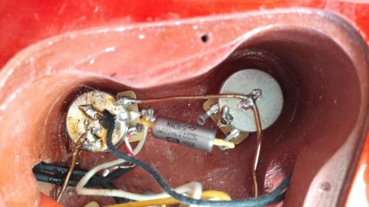
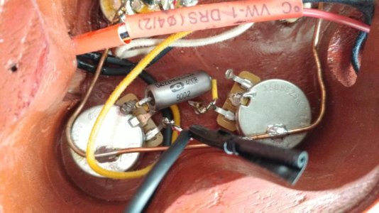
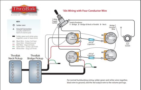
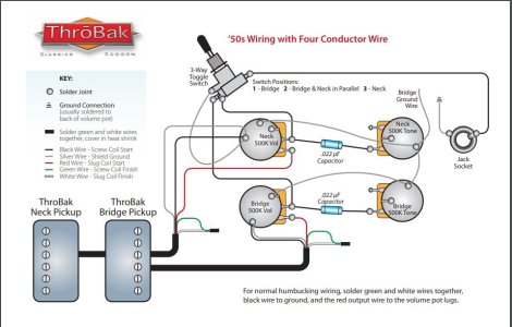
Everything is premium, brand new. CTS 500k pots, PIO russian .22pf caps. Here is few close up pics of wiring. I did it according to 50s diagram.

Multimeter reads 0.5M ohms which is 500K ohms, the value of CTS pot. This is at volume of 10. If i turn down volume, the value drops with pot turns.

wiring50s.jpg


DSC_0158.jpg

DSC_0157.jpg

DSC_0154.jpg

Upper half
DSC_0155a.jpg

bottom half
DSC_0156a.jpg
 

Attachments

  • wiring50s-second.jpg
    wiring50s-second.jpg
    87 KB · Views: 0
Last edited:
Re: Multimeter shows pots resistance instead of pickup resistance when connected to j

Q: Did you use existing pots?

No, new CTS 500k pots. I'm including pictures if it can help identify the problem

Q: Looking from the bottom, is the right-most (CCW) lug of the volume pot connected to ground?

Yes. Right lug soldered onto pot body and there is copper wire that runs across all 4 pots. There was guitar ground wire installed by factory. I've also connected that wire to the back of pots.

Q: Did you use the center lug of volume pot for the output?

Center lug is connected to capacitor .22pf as picture above

Q: Is the CW lug (left-most) of volume pot your input from switch or pickup?

Yes left lug, pictured with white (coil spliting cable) and red (signal) connected together and soldered onto left lug of the pot.


Thank you kindly everyone for help
 
Last edited:
Re: Multimeter shows pots resistance instead of pickup resistance when connected to j

The pickup wiring is as follows

white cable = coil tap
red cable = signal .......white and red are connected together and soldered onto pots leg. If i'm not coil tapping they should be connected together for both coils to work correct?
black = ground
Bare/Copper = pickup shield ground
 
Re: Multimeter shows pots resistance instead of pickup resistance when connected to j

OKKKKK .....so i think i know what the issue may be. I have joined red (signal) and white (coil tap) together and soldered onto LEFT lug of the pot. Did that ground this?

I'm not sure what i am suppose to do with white cable from pickup (coil tap) cable?

Looking at this diagram it's joined with green cable. I have no green cable. I'm assuming this should be just loose (coil tap), not connected to anything?

wiring50s-second.jpg
 
Re: Multimeter shows pots resistance instead of pickup resistance when connected to j

I’m gonna be honest here. That wiring looks scary and appears to have at least one ground loop. Have you considered having the tech do the wiring job too? Looks like you bought good parts and are having other work done. Might be worth a few extra bucks to get it tip-top.
 
Re: Multimeter shows pots resistance instead of pickup resistance when connected to j

Are you installing Throbak pickups? Or just trying to use a Throbak diagram?

If you are installing Throbak pickups, white is not a split wire. By putting white and red on the input, you’ve completely bypassed the pickup and made the slug coil an antenna that won’t produce any sound.

To wire a 4-conductor Throbak as defined in that drawing, red goes to hot, green and white soldered together and taped off not connected to anything else, and black and bare to ground. It even says in the drawing to solder green and white together and cover with heat shrink, if you just read the drawing.

I'm wiring GFS pickups with Kwikplug connector that has 4 wire hence i used throbak diagram for 50s as it's also 4 wire setup. GFS wiring is as follows and my current wiring is as follows.
I think i'm having an issue with wiring of switch to jack. That's not going well i think.

Those are GFS color wiring schemes:
white cable = coil tap -- currently soldered off and tapped off with electrical tape loose.
red cable = signal -- soldered to bottom or left volume pot (that's 50s wiring like in thorbak diagram NOT AS shown in GFS wiring)
black = ground - soldered to back of volume pot
Bare/Copper = pickup shield ground -- soldered to back of volume pot

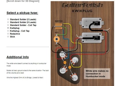
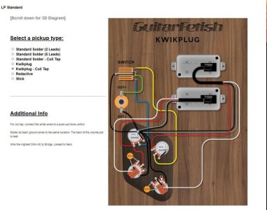
I went to GFS website and they have their own diagrams but it looks like jack plus and minus is backwards in their diagram. I'm posting theirs here.

Now they only have standard modern wiring so hence i used throbak diagram for 50s. The only thing that changes is colors of the wires really, AND THEIR SWITCH PLUS AND MINUS ARE BACKWARDS I THINK?

I regret getting kwikplug. I should have just got 5 wire connector and this would have been so much clearer for me.

https://www.guitarfetish.com/LP-Standard_c_815.html

GFS-WIRING.JPG
 
Last edited:
Multimeter shows pots resistance instead of pickup resistance when connected to jack

For 50’s wiring just swap the tone cap to the center lug. Their jack image doesn’t show the ground touching the sleeve, but you can just look at the part and figure that out.

Throbaks are 5 wire and don’t match GFS, according to all the documentation posted.
 
Last edited:
Re: Multimeter shows pots resistance instead of pickup resistance when connected to j

"Split" not "tap". Totally different. (Even if GFS uses the term "tap", it is NOT a tap.

You've shorted out the pup the way you say you wired it. If you haven't corrected for wire color differences between brands you need to be sure that you follow the wires not the colors (coil "A" start connects to ground; Coil "A" finish connects to coil "B" finish; Coil "B" start is the lead/hot which goes to the vol pot input lug; vol pot output lug goes to switch and to tone pot). When the connection of coil "A" finish + coil "B" finish wires are connected to ground, you have "split" the pup to the "B" coil).

You've lost me. I'm not following that. This is the color scheme and current wiring in my guitar below. What do i need to change and connect to what ?

Total of 4 Cables colors from GFS pickups and their wiring scheme:

white cable = coil split/tap - this is loose and disconnected from everything. Electrical tape is on currently to prevent shorting to other wires/connection in cavity.
red cable = + signal - this is connected to left or bottom lug of the pot (50s wiring)
black cable= - ground - soldered onto back of the pot
Bare/Copper = pickup shield ground - soldered onto back of the pot

What changes should i make?
 
Last edited:
Re: Multimeter shows pots resistance instead of pickup resistance when connected to j

Ok guys i have done complete rewire. I think problem was on switch i had positive soldered onto negative and negative soldered onto positive. Anyhow i can now measure pickups at jack of the guitar.

However there is something odd here. When pots are at max volume 10 it registers 8.4k in neck and 14.4k in bridge, however when i turn pots down to middle it will actually show weird value like 40k ohms, and even somethings 132k ohms.

I'm pretty sure that's not normal unless 50s wiring is doing this. I don't know what to make of that. I will post pics shortly. I'm tired troubleshooting this. I've been at it for 2 full days lol
 
Re: Multimeter shows pots resistance instead of pickup resistance when connected to j

With GFS the colors appear to be the same as Throbak...
Black is the start of the screw coil (-) which goes to ground,
White is the finish of the screw coil AND the finish of the slug coil. Under the tape around the coils of the pickup those two wires are connected to each other and to the white wire that you see. This is the wire that is used to split the humbucker to a single coil (the slug coil). If this wire is taped off/isolated then the two coils of the pickup are in series and are both active and humbucking.
Red is the start (+) of the slug coil and is considered the hot/lead wire which goes to the volume pot input lug.

Your GFS diagram shows Modern wiring. The Throbak diagram shows 50s wiring. It's all a matter of where the tone pot connects to the volume pot.

These are the wires and connections that you see in your diagram. If the white wire is connected to a switch which can connect it to a ground (back of pot) you can split your pickup.
 
Re: Multimeter shows pots resistance instead of pickup resistance when connected to j

Ok guys i have done complete rewire. I think problem was on switch i had positive soldered onto negative and negative soldered onto positive. Anyhow i can now measure pickups at jack of the guitar.

However there is something odd here. When pots are at max volume 10 it registers 8.4k in neck and 14.4k in bridge, however when i turn pots down to middle it will actually show weird value like 40k ohms, and even somethings 132k ohms.

I'm pretty sure that's not normal unless 50s wiring is doing this. I don't know what to make of that. I will post pics shortly. I'm tired troubleshooting this. I've been at it for 2 full days lol

Its normal.
 
Re: Multimeter shows pots resistance instead of pickup resistance when connected to j

With GFS the colors appear to be the same as Throbak...
Black is the start of the screw coil (-) which goes to ground,
White is the finish of the screw coil AND the finish of the slug coil. Under the tape around the coils of the pickup those two wires are connected to each other and to the white wire that you see. This is the wire that is used to split the humbucker to a single coil (the slug coil). If this wire is taped off/isolated then the two coils of the pickup are in series and are both active and humbucking.
Red is the start (+) of the slug coil and is considered the hot/lead wire which goes to the volume pot input lug.

Your GFS diagram shows Modern wiring. The Throbak diagram shows 50s wiring. It's all a matter of where the tone pot connects to the volume pot.

These are the wires and connections that you see in your diagram. If the white wire is connected to a switch which can connect it to a ground (back of pot) you can split your pickup.

Thank you for explanation. I think it's same thing that Thorebak diagram says. I'm just new to all this so terminology is new to me. Maybe i'll order push/pull pots and redo it for coil splitting, when i'll feel ambitious about it. Might as well do it for $20.

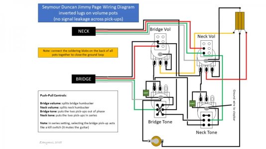
I was thinking of doing Jimmy Page wiring but that's not possible i think? , as GFS Kwikplug pickups are missing Green wire. The only available option is this which is fine as well. So here i can only do 2 push pulls.

Lesson learned for next time ONLY TO BUY 5 wire pickups.

Many thanks again to everyone that helped me. Much appreciate it.

gfs-wiring-coiltap-standard.jpg

Someone in other thread attempted to do this with 4 wires and i think based what they wrote they were successful. I'm hesitant to try this after my experience lol

I'm assuming the green wire in this diagram is my white wire, the coil splitter wire?

JP-SD-2.jpg
 
Last edited:
Re: Multimeter shows pots resistance instead of pickup resistance when connected to j

Your coil split wire is two wires in a 4 conductor pickup. Its merely an extension of the series connection......the two wires that would get soldered together if you didn't want any splits.
Similarly, if you don't want to split the pickups, this one gets taped off and not used.

Alex so can i use last diagram and use white wire instead of green in that diagram. the silver is bare wire i think and rest is same.
 
Status
Not open for further replies.
Back
Top