Need advice for P90 swap

FrenchCanada

New member
Would you guys this project is even doable? I'm looking at the connections but there are no lugs. The black wire splices off and connects to the mini-board. Would that be the ground I am thinking? Please tell me what you can analyse.
 

Attachments

  • IMG_0100.JPG
    IMG_0100.JPG
    32 KB · Views: 0
  • IMG_0101.JPG
    IMG_0101.JPG
    41 KB · Views: 0
I think i understand the connection. The inner wire for the p90 junctions off underneath and over the other side of the mini-board further back and the ground casing is extended with a lot of solder straight ahead. I still don't understand why the mini-board has no lugs?
 
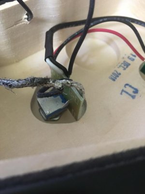
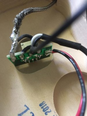
PCB's traditionally don't have lugs but holes with solder pads. Connect the replacement pickup same was as you see here and you're good. The inner wire of the P90 is hot, the outside braid is ground.

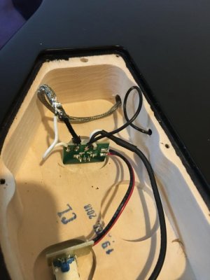
There are better ways of grounding braided wire. One way is to take a short piece of thinner wire, 22AWG is fine, and strip it on both ends, one end about 1/4 to 1/2 inch. Tin both ends with a small amount of solder. Now, wrap one end of it around the braided pickup wire near the end and solder it in place. Then solder the other end of the 22AWG wire to the ground point on the switch. Much neater, less solder and heat involved, and a heck of a lot easier to work with.
 
ErikH thanks for your help. I was able to solder the p90 to the PCB. Tricky because the connection was laying vertical and made good use of my helping hands. I've included a photo.
 

Attachments

  • IMG_0130.JPG
    IMG_0130.JPG
    40.4 KB · Views: 0
Thank you Seymour Duncan for the instructional videos and unbeatable equipment. I am stoked because my guitar plays and sounds like a 2000$ guitar now.
 
Back
Top