Peavey Windsor Effects Loop/Boost Issue

Re: Peavey Windsor Effects Loop/Boost Issue

Great for modding too.

I may reach out to you at some point regarding that if you don’t mind?
I’m interested in beginning to learn more about amp circuits. That’s actually one of the reasons I bought it. But I need to look into what types of mods are available. I’m a noob.
 
Re: Peavey Windsor Effects Loop/Boost Issue

I may reach out to you at some point regarding that if you don’t mind?
I’m interested in beginning to learn more about amp circuits. That’s actually one of the reasons I bought it. But I need to look into what types of mods are available. I’m a noob.
Yes, fine.
Here's a popular one. - https://www.aronnelson.com/gallery/main.php/v/DougH/amp/windsor/ -
There's a few threads here [ at SD ] that have modding info in them.
 
Re: Peavey Windsor Effects Loop/Boost Issue

Ok I plugged the send into a practice amp I got lying around. All I hear is a buzz. The cab that Windsor is hooked up to sounds fine though as I strum my guitar.

Bit of a noob question but when I take voltage readings, is the standby switch supposed to be on or off?


Sent from my iPhone using Tapatalk

With the 24v and 12v feeds and what they feed, no difference on or off.

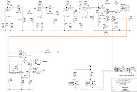
This is the signal path [ red high light ] PWsignal path.jpg
. If there's still nothing, I'd say nothing is getting through that transistor and it needs replacing.
here's a link to a cross reference guide [substitutes ] for Peavey transistors, - https://www.scribd.com/doc/29319120/Peavey-Semiconductor-Cross-Reference-List - substitutes might be easier to get.

It's listed as SK3919, not SKA3919.

Is the foot switch still lifeless ?
 
Last edited:
Re: Peavey Windsor Effects Loop/Boost Issue

With the 24v and 12v feeds and what they feed, no difference on or off.

This is the signal path [ red high light ]
. If there's still nothing, I'd say nothing is getting through that transistor and it needs replacing.
here's a link to a cross reference guide [substitutes ] for Peavey transistors, - https://www.scribd.com/doc/29319120/Peavey-Semiconductor-Cross-Reference-List - substitutes might be easier to get.

It's listed ass SK3919, not SKA3919.

Is the foot switch still lifeless ?


Thanks I'll order the replacement and let you know how it goes. Looks like Amazon carries 2N3391A and arrives on Tuesday!

The footswitch is indeed still lifeless.
 
Last edited:
Re: Peavey Windsor Effects Loop/Boost Issue

Thanks I'll order the replacement and let you know how it goes. Looks like Amazon carries 2N3391A and arrives on Tuesday!

The footswitch is indeed still lifeless.
Maybe test for voltage at R60 and R61 [both sides] and test R37 [ 10 Ohms/ on the remote switch board] The remote switch grounds those relays to make them function. If you have 24v at the relay, ground the other side with a test lead and it should switch as you connect/ disconnect it.[ you should be able to hear it switching]
 
Last edited:
Peavey Windsor Effects Loop/Boost Issue

Maybe test for voltage at R60 and R61 [both sides] and test R37 [ 10 Ohms/ on the remote switch board] The remote switch grounds those relays to make them function. If you have 24v at the relay, ground the other side with a test lead and it should switch as you connect/ disconnect it.[ you should be able to hear it switching]

R60 and R61 both have 26.5 @ 200m on both sides. Traced voltage from the relay all the way to the remote switch board and it’s reading the same.
R37 reads 0.5 on one side and nothing on the other.

Working on testing the relays. Do I need to remove them to test it. What do you mean “ground the other side with a test lead”? Do I keep the one probe on ground and then touch the other side of the relay with my red lead? Sorry. Never tested a relay before.
Another question. Is there tube that would affect the loop and boost? I mentioned I swapped out the 12ax7s to test but to no avail.

Sent from my iPhone using Tapatalk
 
Last edited:
Re: Peavey Windsor Effects Loop/Boost Issue

Also I opened up my footswitch and connected to the amp. I do read 26.5 coming to both switches.


Sent from my iPhone using Tapatalk
 
Re: Peavey Windsor Effects Loop/Boost Issue

R60 and R61 both have 26.5 @ 200m on both sides. Traced voltage from the relay all the way to the remote switch board and it’s reading the same.
R37 reads 0.5 on one side and nothing on the other.

Working on testing the relays. Do I need to remove them to test it. What do you mean “ground the other side with a test lead”? Do I keep the red probe on ground and then touch the other side of the relay with the other end of the red lead. Sorry. Never tested a relay before.
Another question. Is there tube that would affect the loop and boost? I mentioned I swapped out the 12ax7s to test but to no avail.

Sent from my iPhone using Tapatalk
Yes [ of course you'll have to take the lead out of the multi meter ], no need to remove the relays. No there are no tubes interacting at this area [ Send/Return/Switching ], just that one transistor.

R37 reads 0.5 on one side and nothing on the other.
i meant test it's Ohmage, should be 10 Ohms.

I did mean this when I referred to "test leads " but you probably don't have any so improvising with a multi meter lead should do.

41t3RmIXnSL._SX342_.jpg
 
Last edited:
Re: Peavey Windsor Effects Loop/Boost Issue

Thanks! R37 did read 10 ohms. Testing the relays now.

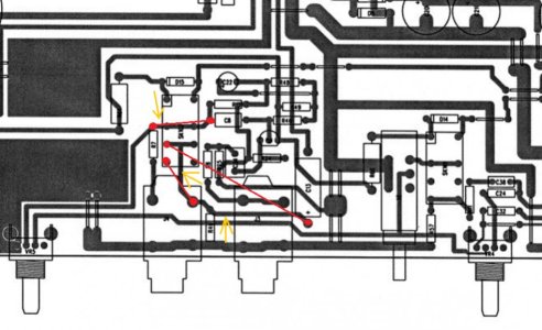
Hate to throw a wrench in the whole damn thing but....uh...this doesn’t look stock to me.

f4b8d426d1039977931e0755fc158603.jpg


Sent from my iPhone using Tapatalk
 
Re: Peavey Windsor Effects Loop/Boost Issue

Hmm, yes. There's a cut track there as well as those added wires. Not sure what that all does though but it sure looks like some sort of modification.
Are they the Send and Return jacks at the top there [ black ].
Thanks! R37 did read 10 ohms. Testing the relays now.

Hate to throw a wrench in the whole damn thing but....uh...this doesn’t look stock to me.

f4b8d426d1039977931e0755fc158603.jpg


Sent from my iPhone using Tapatalk
 
Peavey Windsor Effects Loop/Boost Issue

Hmm, yes. There's a cut track there as well as those added wires. Not sure what that all does though but it sure looks like some sort of modification.
Are they the Send and Return jacks at the top there [ black ].

Yep. That’s probably the reason it crapped out in the first place when I plugged in the footswitch.

Also, I tested the relays and they are not switching.

Sent from my iPhone using Tapatalk
 
Last edited:
Re: Peavey Windsor Effects Loop/Boost Issue

The schematic I have also has the board layout diagrams. I'll see if I can figure what that is doing and what it should be. That might take a bit of time.
 
Re: Peavey Windsor Effects Loop/Boost Issue

Thanks! R37 did read 10 ohms. Testing the relays now.

Hate to throw a wrench in the whole damn thing but....uh...this doesn’t look stock to me.

f4b8d426d1039977931e0755fc158603.jpg


Sent from my iPhone using Tapatalk
I've seen this on quite a few of these and am positive it was done at the factory.

I actually owned 2 of these amps that I bought new...the 1 I bought when they first came out did not have this added wiring, but the 2nd one I bought a year later did.

I'm not sure what caused them to do that but I never had a problem with either amps' fx loop or boost functions. I also never saw any revisions to the schematics to denote the change.


Sent from my SM-N950U using Tapatalk
 
Peavey Windsor Effects Loop/Boost Issue

I've seen this on quite a few of these and am positive it was done at the factory.

I actually owned 2 of these amps that I bought new...the 1 I bought when they first came out did not have this added wiring, but the 2nd one I bought a year later did.

I'm not sure what caused them to do that but I never had a problem with either amps' fx loop or boost functions. I also never saw any revisions to the schematics to denote the change.


Sent from my SM-N950U using Tapatalk

Oh man I’m glad to hear that! Thanks for chiming in!


Sent from my iPhone using Tapatalk
 
Last edited:
Re: Peavey Windsor Effects Loop/Boost Issue

I've seen this on quite a few of these and am positive it was done at the factory.

I actually owned 2 of these amps that I bought new...the 1 I bought when they first came out did not have this added wiring, but the 2nd one I bought a year later did.

I'm not sure what caused them to do that but I never had a problem with either amps' fx loop or boost functions. I also never saw any revisions to the schematics to denote the change.


Sent from my SM-N950U using Tapatalk
Thanks for that. It'll help me figure what's going on there.
 
Re: Peavey Windsor Effects Loop/Boost Issue

I've been a bit busy to get to this.
When you turn the amp on , do you hear the relay switches click over [ or when you turn it off ] ?
 
Back
Top