Push-pull mod but in 50s wiring?

AllHailDIO

New member
Hello
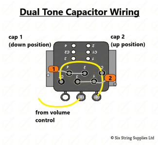
I found this cool mod on Six String Supplies. It is a dual capacitor mod which allows you to switch between two different capacitors via push-pull Tone knob. But the diagram is for modern wiring.

Is it possible to change this mod to 50s wiring? The common connections (c1 and c2) to lug 3 is what's throwing me off. Can I solder that to lug 1 instead or will that reverse my taper? Can I solder to lug 3 as well as my connection to the Volume pot, or will that pose a problem? I'm not sure the purpose of these common connections to a lug.

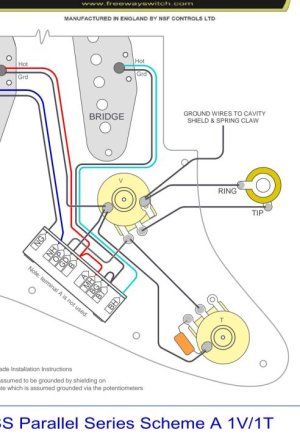
My guitar is a 1 vol, 1 tone Strat and I would like to use a Freeway 10-way switch if that's any constellation.

Thanks!
 

Attachments

  • 2-tone-capacitor-push-pull-pot-wiring_2048x2048 (1).png
    2-tone-capacitor-push-pull-pot-wiring_2048x2048 (1).png
    36.4 KB · Views: 0
  • Screenshot_20240219_011117_Microsoft 365 (Office).jpg
    Screenshot_20240219_011117_Microsoft 365 (Office).jpg
    51.1 KB · Views: 0
For the 50's mod, it's only the yellow wire that says "from volume control" that matters. Do red line for modern wiring, and green line for the 50's mod.

Also, they did that way too complicated. I'll show a much easier way after I get some coffee in me. What are the two cap values?

50's-tone-push-pull.png
 
What they are doing is Fig 1. And there's nothing wrong with it per se. But it has a couple minor cons. As you switch from one cap to the other, there's a brief moment where there's no cap in the circuit. Granted, it will probably be 5 to 10 ms, but if you're playing loud, at high gain, it might be a "pop." Also, it wastes one side of the switch.

If you do Fig 2, you always have at least one cap in the circuit. And, it frees up the other side of the switch. So, for example, you might want to use the other side to split a humbucker. You'd have one cap value when it's split, and another when it's a humbucker.

The "con" of fig. 2 is that you have to do a teensy bit of math. The smaller cap value is when the switch is down. And the two add together when the push-pull is up. For example, two .022 uf's would give you .022 and .044. A .010 uf and .022 uf would give you a subtle .01 and a beefier .032.

Both methods are fine. It's just nice to have options.

Cap_Switcher_Mod.png
 
Hey Artie! I recognize your name and just want to say thanks for your help here (and numerous other times for other people, you've helped me many times indirectly).

:yourock: (Been awhile since I've been on here and missed these nostalgic smilies lol)

The cap values, I'm thinking 0.22 and either 0.33 or 0.47. I'm mainly interested in the cap type. I know that's backwards to how most people do this mod considering the values are more imperative, and I guess I'll see for myself. I plan to do an Orange Drop 225 and a Malory 150. They are my favorite two caps but IMO have different enough tonal character.

That said, I'm a little confused and this may just be my lack of knowledge showing. I thought 50s wiring always used lug 3 for a capactor and lug 2 for ground, so I assumed a modified diagram would reflect this in some way but I do not see that.

​​Do you mind explaining? Not that I do not believe you but I seek the power of knowledge:22: This all kinda reminds me of like how lightsabers and The Force works in Star Wars. Honestly, there's a charm of not knowing so maybe that's a bad example lol, but what I mean is, this too (electrical components & diagrams) have always mystified me :33:​​​​​​
​​​​

 
don't get me wrong but are you sure you want to do so much work just for the value of the cap? the real difference will be on the extreme setting only, I guess with the larger one you can obtain the same sound of the other , just in a different position.
 
don't get me wrong but are you sure you want to do so much work just for the value of the cap? the real difference will be on the extreme setting only, I guess with the larger one you can obtain the same sound of the other , just in a different position.

Yep. I wouldn't say soldering is easy but I def wouldn't consider it much work either. I have the dexterity but it is the cerebral part (schematic) that is the difficult for me lol a common theme for me :lmao:

I used to have a Mallory 150 on the neck tone pot. IMO it has its own vibe but when fingerpicking, I felt my attack transient was compressed in an indistinct way. Swapping in the Orange Drop added more fidelity and I can hear and feel the notes better when fingerpicking. But I do miss the Mallory tone at times, especially with the treble rolled off.

I don't think the Orange Drop sounds much different than other caps, but I do find Mallory to be more distinct than all others. More lo-fi, perhaps even inefficient to an audiophile's definition, but for a guitarist, at least myself, I find their character as charming. I quite love it, just not what I want all the time.

That said, I am a bedroom player. I'm not playing live where such nuances would not easily be heard. I hear these nuances and appreciate them when playing. Soldering and experimenting to discover things that I enjoy is a non-issue.

​​​​​​
​​​​​​
​​​
 
the value of the cap controls the knee frequency as far as i know, which means different values roll off different frequencies, a .015 cap doesnt sound like a ,047 cap regardless of setting
 
the value of the cap controls the knee frequency as far as i know, which means different values roll off different frequencies, a .015 cap doesnt sound like a ,047 cap regardless of setting

I think you're correct. That's how I've always understood it.

BTW my previous observations regarding Malory 150 and Orange Drop are of the same value, at least printed value as I didn't measure them.

But this is getting off topic lol. I'm curious how to wire this mod in 50s wiring. Artie provided a schematic but I had always been under the impression that 50s wiring always had lug 2 grounded and lug 3 with the cap & connection to volume pot, so I'm curious how that all works. I wouldn't mind someone tutoring me on the technical details because I wish I could see a diagram and understand what's going on. I want the knowledge :fingersx:
 
the value of the cap controls the knee frequency as far as i know, which means different values roll off different frequencies, a .015 cap doesnt sound like a ,047 cap regardless of setting

Exactly. (Where's freefrog when we need him?) The cap value determines where you start rolling frequencies back. The pot value determines the magnitude of that roll back.

The 50's mod is completely different. With that mod, the impact of the tone circuit, removes itself from the equation as you roll the volume down. Make sense?
 
Hey Artie & Marcello, really not sure my contribution is needed but I agree with what Artie said : the knee frequency is set by the value of the tone cap + the inductance of the pickup. And the value of the tone pot defines the amplitude of the resonant peak (itself set by the inductance of the pickup + capacitance of the whole wiring)...

While I'm at it: I hadn't found the time to click on "like" for the posts 2 & 3. It's done now - always appreciate these helpful and tasteful schematics that Artie shares here and there. You lucky man AllHailDIO! ;-)
 
Do y'all mind if I pick y'all brains? What is the purpose of the lugs on a potentimeter? Are they all the same, in lamen terms, and their differences only begin to occur with the schematic? Like, its interactive and per schematic, rather than a fixed function?

Artie is a legend. I don't post here often but I remember coming across his de-mud mod a long time ago. One of the best things I've found on the Internet!
 
What is the purpose of the lugs on a potentimeter?

Those are the three terminals. The "outside" two are simply a resistor. The middle one is the magic. It evolves with your fingers. That's how we get volume and tone controls.

Technically . . . a voltage divider.
 
Hey Artie & Marcello, really not sure my contribution is needed but I agree with what Artie said : the knee frequency is set by the value of the tone cap + the inductance of the pickup. And the value of the tone pot defines the amplitude of the resonant peak (itself set by the inductance of the pickup + capacitance of the whole wiring)...


do you have an equation for q and f please ? the classic first order RC filter comes to my mind but being there a L it's a a bit complex, it's a second order I think
 
To know at which frequency a pickup resonates when paired to a tone cap or not, I'd just use the following tool (under the basic equation that I was about to share):

https://www.petervis.com/Radios/par...ator/parallel-tuned-circuit-calculator-f.html

To know the resonant frequency once the tone pot at zero, enter the inductance of your pickup (example: 2H for a CS69 single coil, 4H for a P.A.F. clone) then set C @ 0.022 Farad or whatever tone cap value you want .

To know the resonant frequency with pots full up, keep the inductance of the pickup and just set C much lower to reflect the parasitic capacitance of the pickup itself + its pots and wires + the guitar cable used (example: 100pF of coil(s) + 20pF of wires + 10pF per pot and jack plug + 450pF from guitar to input).
The resistance of the pots will change the height of the resonant peak but not really the resonant frequency (at least with the kind of resistive loads most often present in parallel with pickups).

There are various ways to know the Q factor and when it comes to guitar pickups, it's most often calculated @ 1000hz but I find the related equations rather indifferent if not misleading, personally. To avoid any petty post about that, let's just share a link toward a reliable doc with further explanations:

https://www.gitec-forum-eng.de/wp-content/uploads/2019/03/poteg-5-5-4-resonance-q-factor.pdf

HTH. :-)
 
Back
Top